

Under the Red Top
making the best of life & wood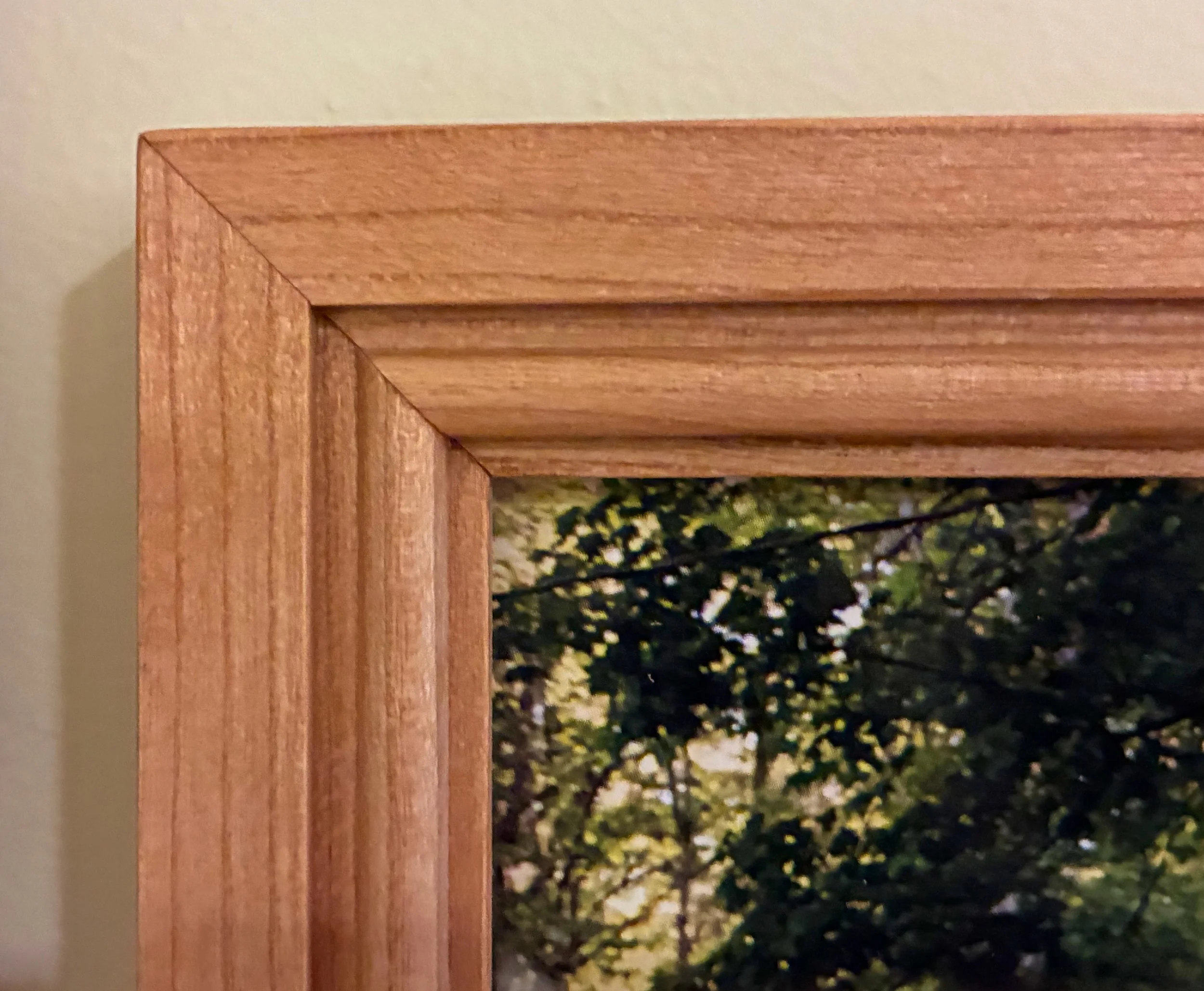


Branching Out

Another year under the Red Top and time to reflect on that newly formed ring.
Incremental mass
First, the facts. Along with a few accessories for our home and some items crafted for family & friends, 8 capital “P” Projects were completed during the year (plus, the No. 220 is well on its way). Not a bad year. I’d say the Ledger chest was my favorite piece, followed closely by all the rest. Included in these are a garden structure and a “winged animal” house, the construction of which are now becoming annual traditions.
Those are the quantitative metrics, easily compared year over year. Qualitative metrics also count, and these come from the new techniques and lessons picked-up along the way. For instance, when the year began I had yet to construct my first drawer and now I have made nine. Sliding doors (2), a sliding lid (1), panel edged boards (11) and finger jointed corners (4) were also fashioned for the first time in 2022. Learning new skills is the most rewarding part of the workshop experience for me; that, and capturing the thrill of it all in this forum. Upon reflection, I probably last acquired manual skills during my graduate research days, and then spent the subsequent “working” years applying those in and around the chemistry laboratory. It feels good to again be in a realm where there is room to grow.
New Growth
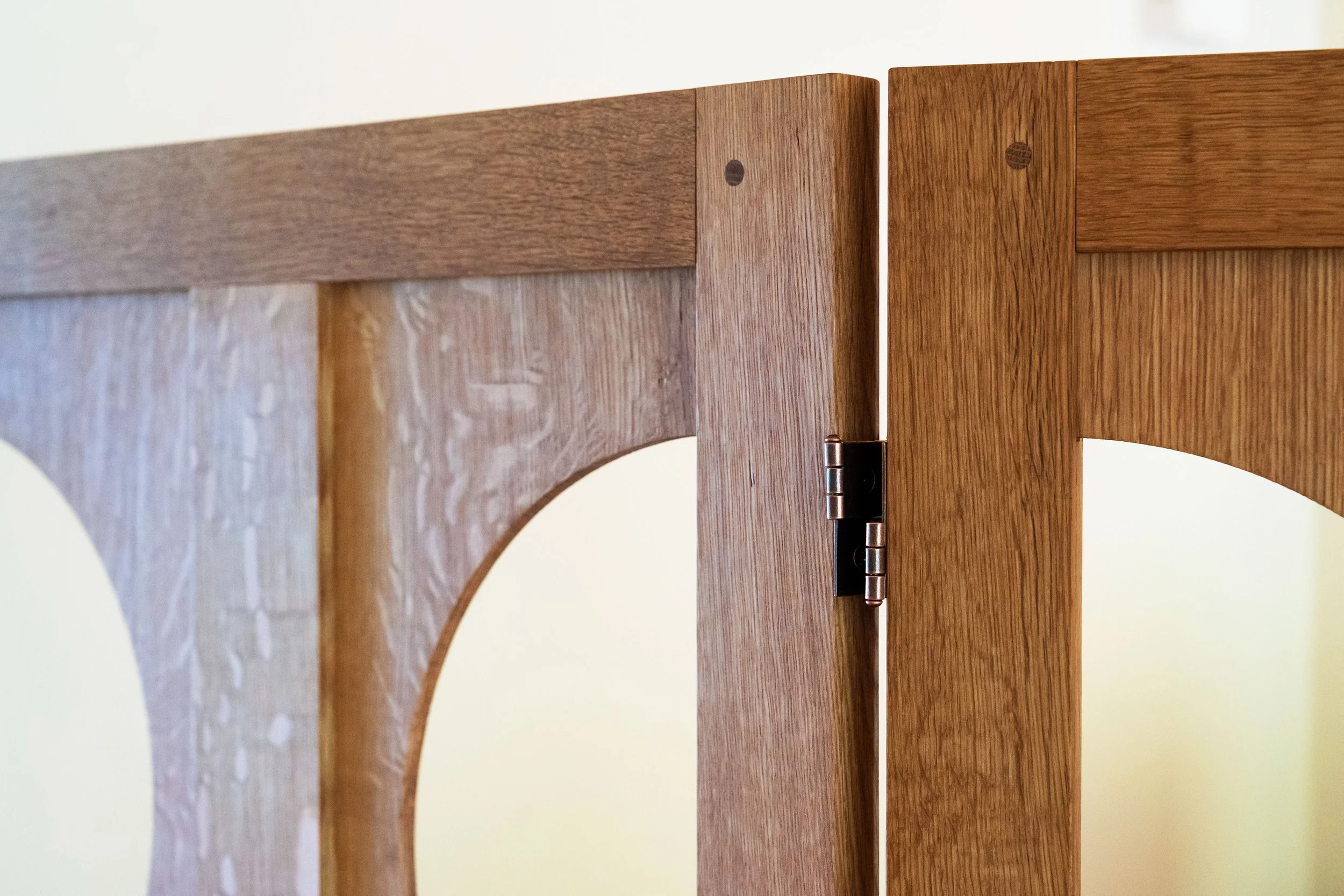
The Red Top Workshop sits in Harvard, Massachusetts but its roots emanate from the opposite hemisphere. “Asian Inspired Furniture” is the tag line on the website and East Asian furniture design was the inspiration for nearly everything built during my first few years as a woodworker. This theme was continued in 2022 with completion of the Ledger chest (Japan) and Stationery chest (Korea), but a new style has gained my interest based on the Arts and Crafts movement of the late nineteenth and early twentieth centuries. English Arts and Crafts furniture design, and its American cousins, “mission” and “Craftsman”, produced beautiful furniture that relied on simple construction, meaningful features and robust materials as their raison d'être. Conceived as a response to the overly ornate Victorian styles, Arts and Crafts furniture also happens to share many characteristics with the simple, straight-forward works of Korea and Japan. Previously, I have commented on the genius of Gustav Stickley and the influence of his Craftsman designs on American furniture, and will likely have more to say on the Arts and Crafts pioneers as I continue my research. The aesthetic is so compelling to me that it is sure to populate future work.
In fact, I may need to re-brand so as to include this broader interest into the identity of The Red Top Workshop. That, too, is a satisfying aspect of furniture making; the ability to respond to developing interests by applying previously acquired skills to the creation of new motifs. If you think about it, that’s how a tree shapes itself over time, developing branches where the light is best. And thriving in the process.
Happy New Year!


No. 220: the frame

The framework of most sofas is rarely seen nor thought of. Buried beneath padding and fabric, it performs its supporting role dutifully in the dark. And that’s just as well, for what you would see in the light would be unremarkable materials held together by the occasional wooden joint and various metal fasteners. Not judging. It’s the way frames are built when meant to be covered. The settles of a century ago were different, though. Supported by exoskeletons, there was no place to hide slapdash construction. In fact, their bones defined their being; upholstery was just a pretty gown. Even if Craftsman style is not your taste, you have to admire the honest presence of this furniture.
Gustav Stickley settle (No. 208) with pegged mortice & tenon joinery
The Craftsman, Vol. V, 4 (1904), p.407
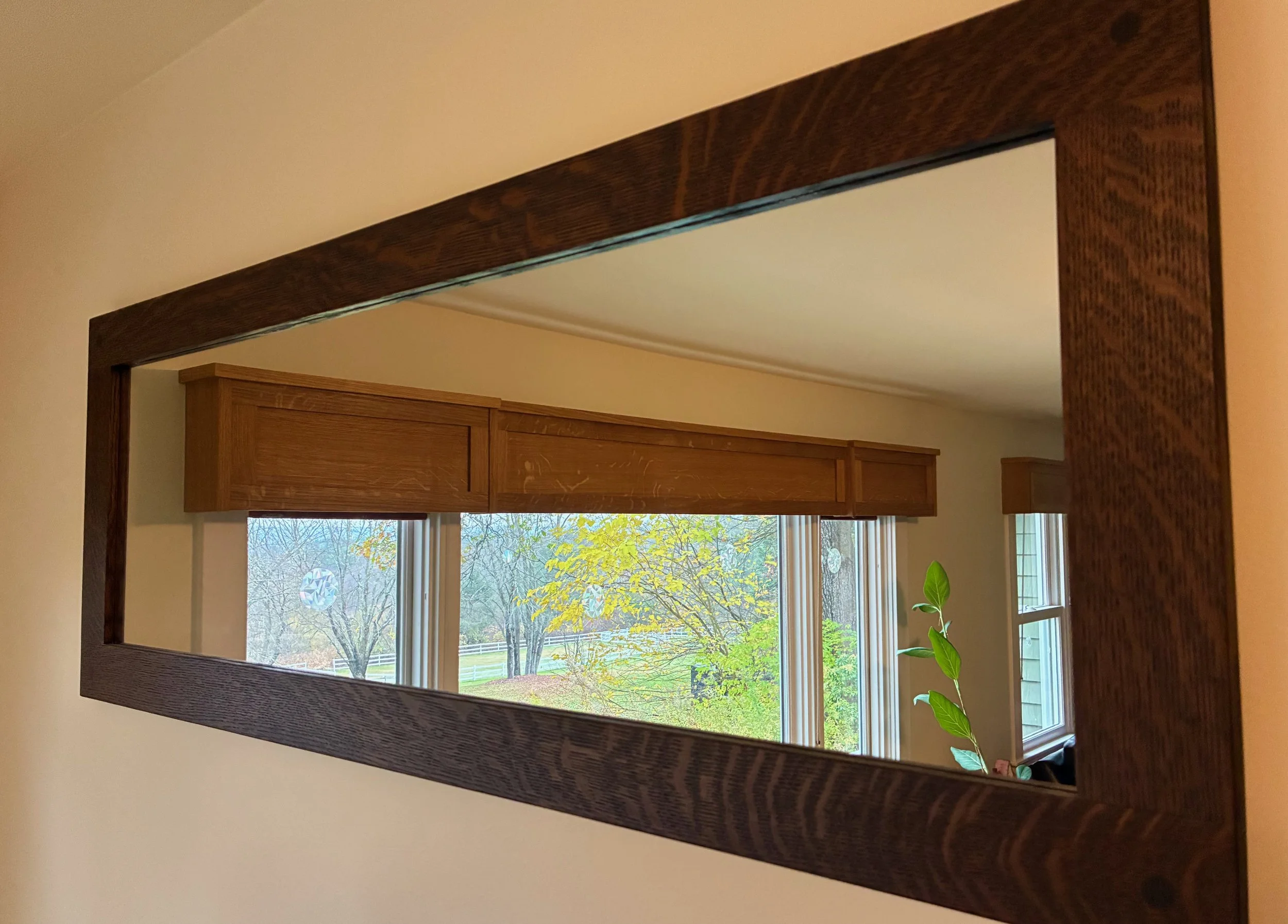
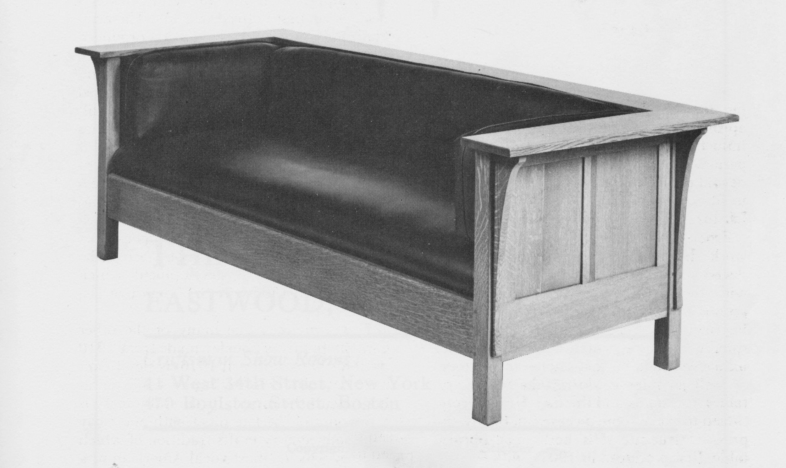
The framework on our Project is different from these early examples, but just as forthright. Instead of the typical slat design, panels wrap the exterior of L. & J.G. Stickley’s No. 220 - like the walls of a boardroom. And then there are the arms! Built to serve, the massive arms impart an air of opulence while surrounding you in coffee table comfort. I find them to be both ingenious and beautiful - by design.
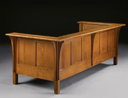
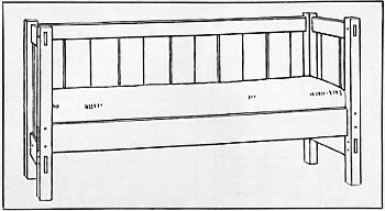
L. & J.G. Stickley’s No. 220 settle
reproduced from the online auction site: artnet.com
Completing the frame for No. 220 involves routine mortice & tenon and framed panel joinery, the challenge comes from scale. This thing is large; definitely the largest piece of furniture I’ve ever built. So to break the work into manageable portions, construction was approached as a sequence of “jobs” described below.
Job 1: Rails
Framed panel construction, commonly used to make things like doors and dressers, involves 3 components: stiles (the vertical members); rails (the horizontals); and the panels, themselves. Typically the stiles and rails are attached to one another through joinery and glue, while the panels float freely within this construct. In addition to 4 legs, the No. 220 settle contains 13 stiles and 7 rails, all of which will need to be dimensioned and then joined together. These are the joints that create the frame and, as such, should be fashioned with care.
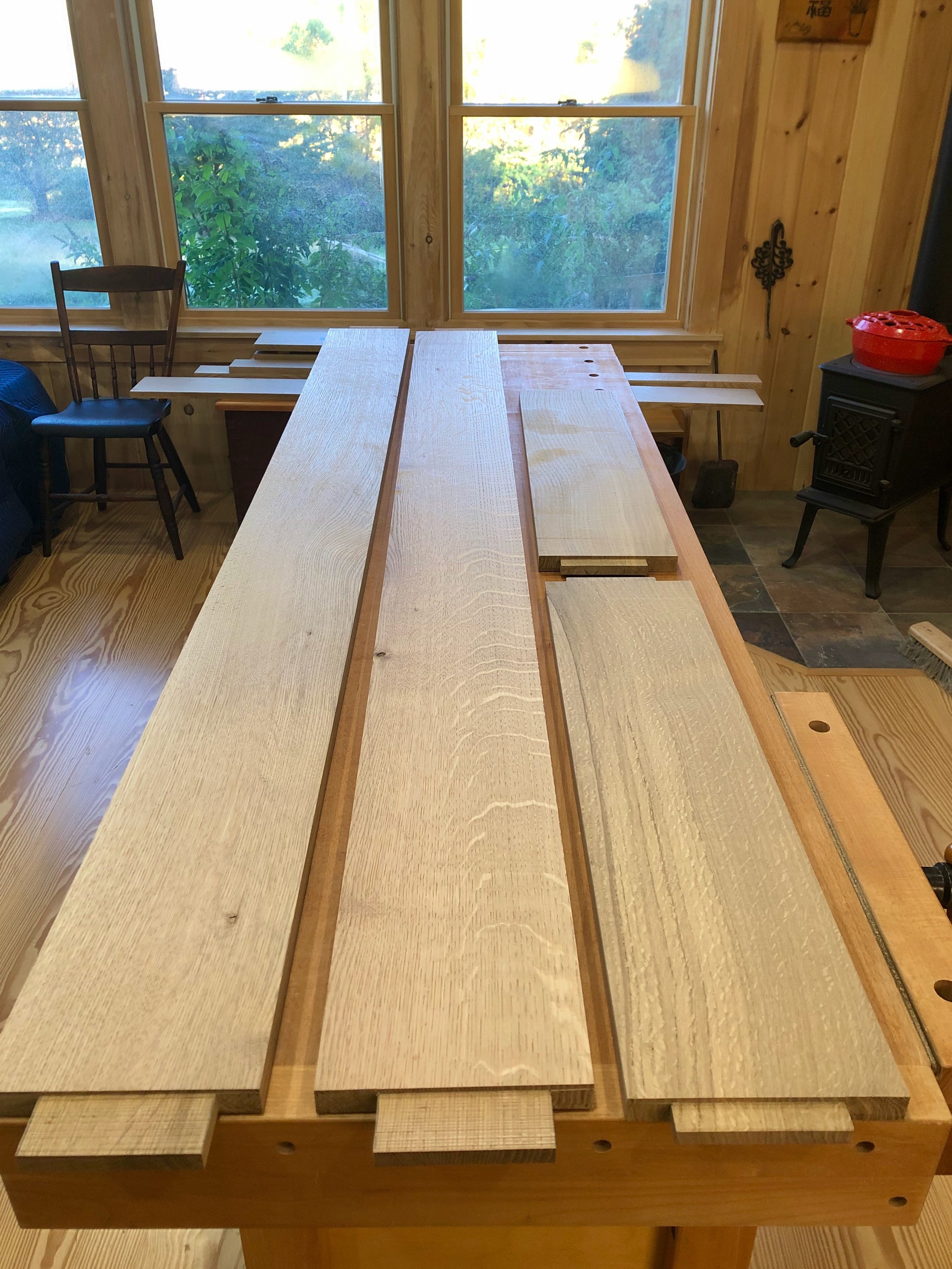
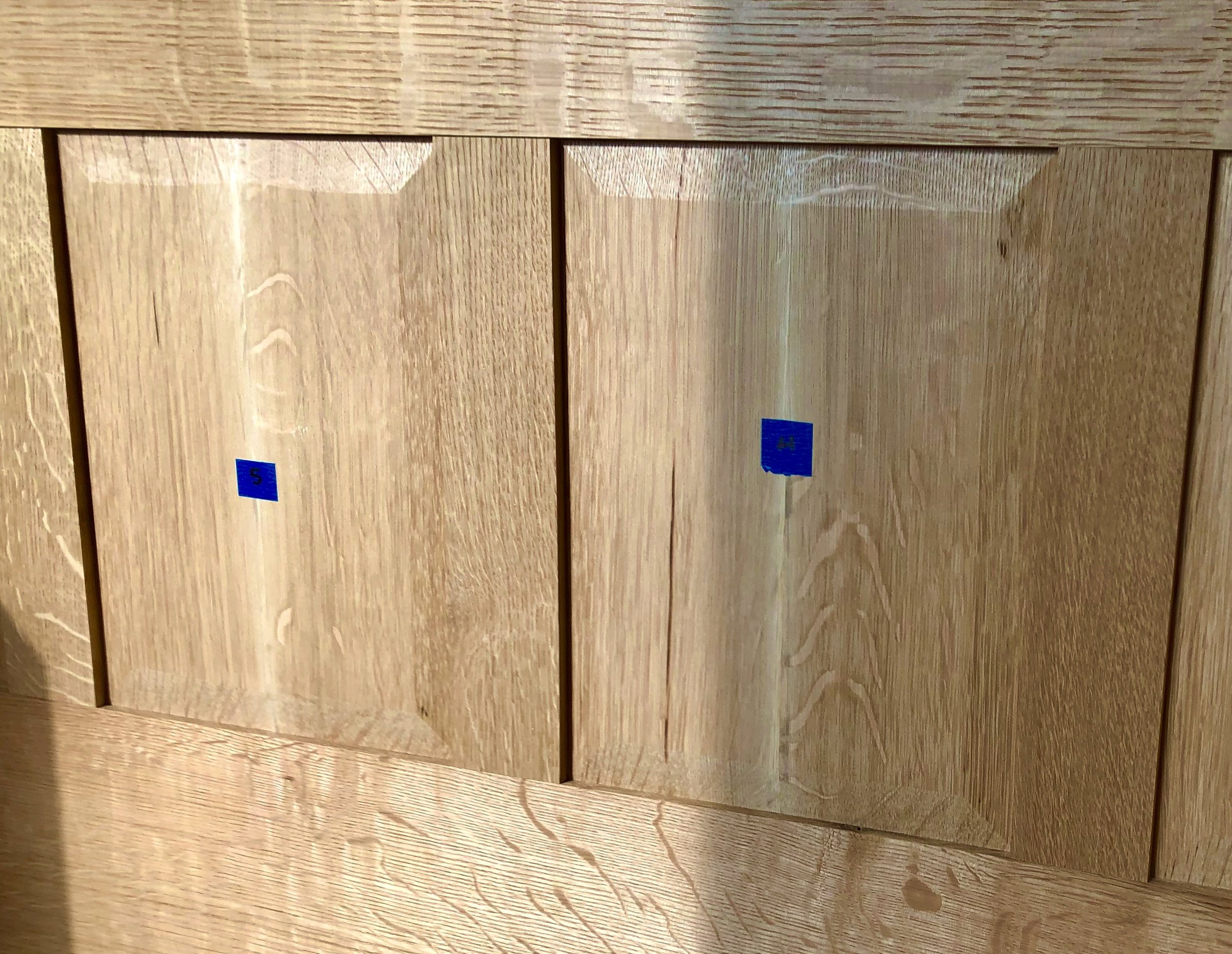
The job begins by prepping the rough 4/4 boards to make them smooth, straight and square. Now, it turns out that a stack of rough lumber “is like a box of chocolates …”. While one can make visual assumptions as to the grain and ray fleck pattern beneath the fuzzy exterior of our quarter sawn oak, it is only when boards are planed that they express their true “flavor”. Generally, a smoothened quarter sawn board reveals something rich and satisfying, but occasionally a fruit-filled one will turn up. (Let’s face it, we all hate when that happens.) Thus, I decided that before I commit stock to becoming stiles, rails & panels I should probably have a taste of every board and then classify them by character. Assuming proper dimensions, the showiest pieces would become panels, and the more modest ones the stiles, rails and corbels. In addition to rays and grain, color and the presence of natural defects (e.g., knots) are also a consideration. Eventually, this wood will be finished with stain and varnish where more visual surprises await, but for now I was content to make the best choices and move on.
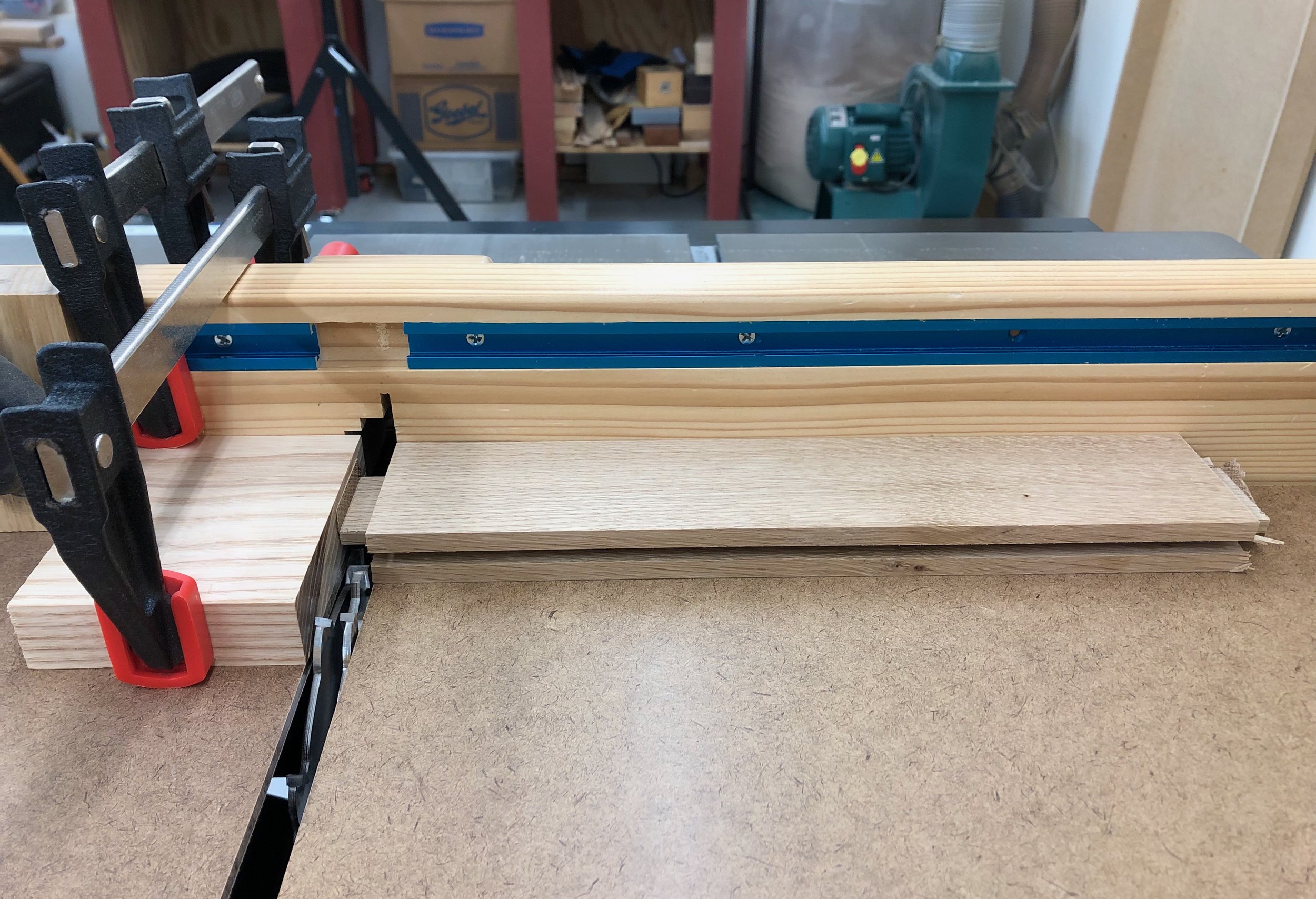
As a final obstacle, one of the 75 inch long rails would need to come from a board that was heavily curved along both of its edges In order to charm this snake I utilized a straight piece of maple trim material, found abandoned in my basement by a previous homeowner. This 8 ft. long “guide” was screwed along one edge of the oak board, protruding at least 1/4 in. all along the way. I could then ride that guide along my table saw fence during a rip cut to produce a straight oak edge on the opposite side. Removal of the guide then put this board on par with the rest of my stile & rail stock, which were then all jointed/ripped and chopped to size.
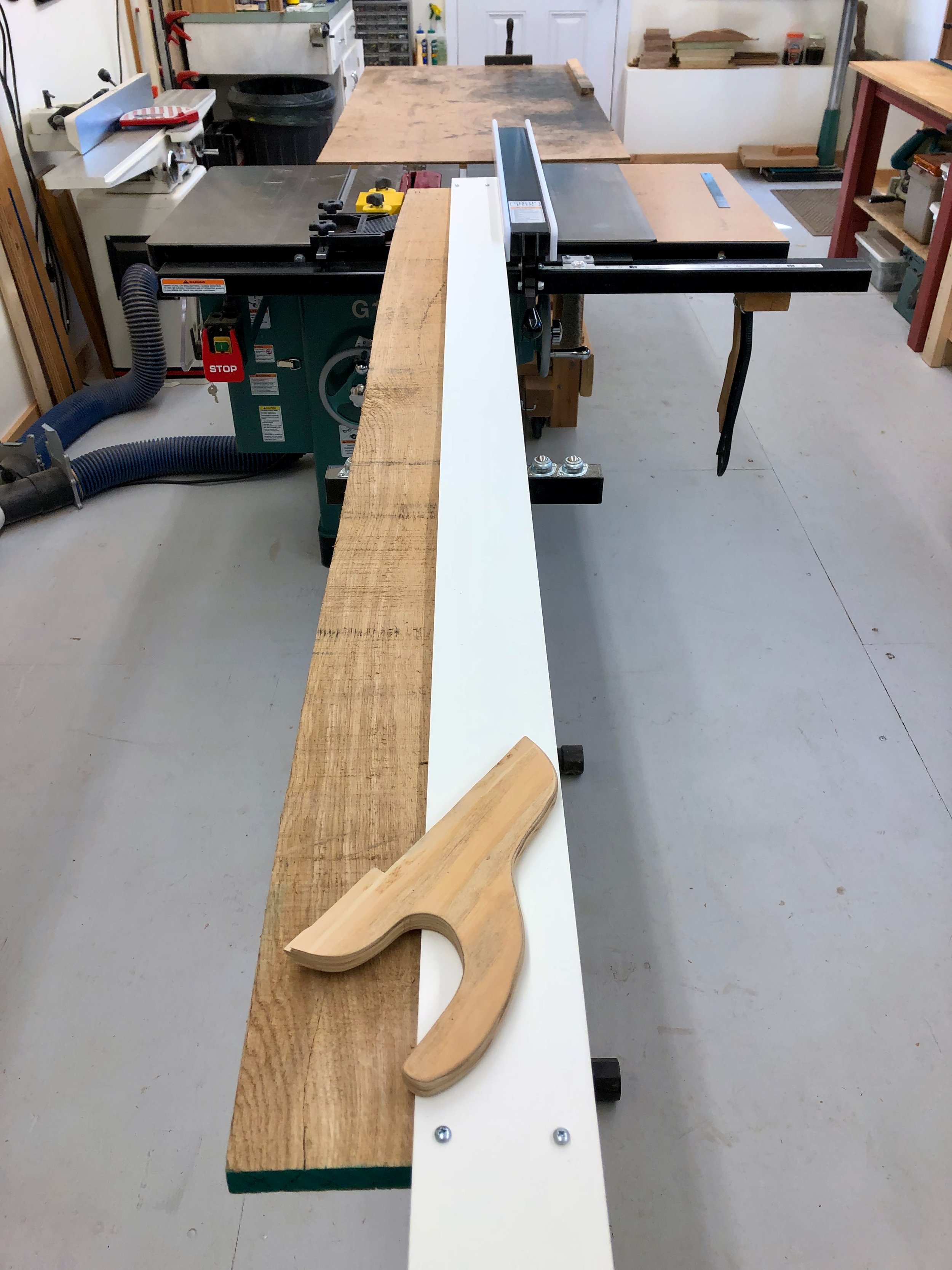
Riding the guide (in white) to straighten a wayward rail at the table saw
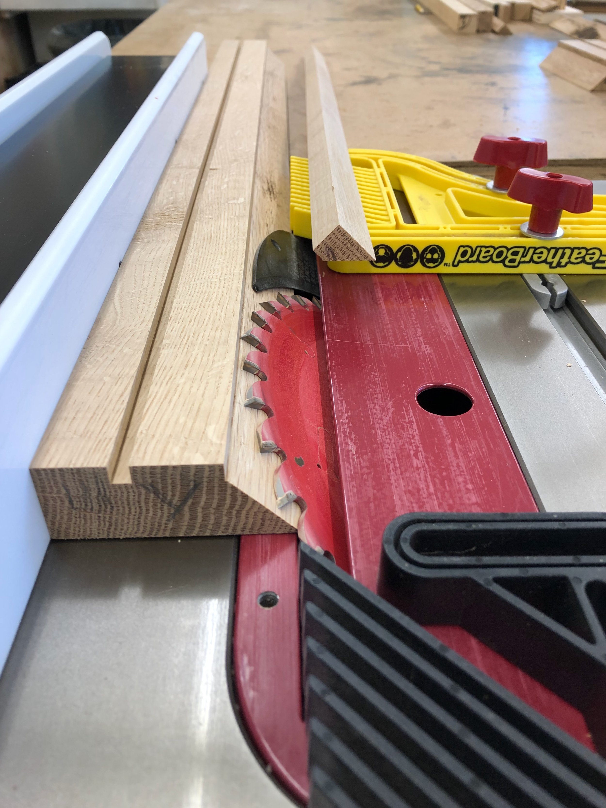
Now that the boards have been assigned their role and rough dimensioning achieved it was time to cut tenons on the rails. The bottom rails are a full 6 1/2 inches wide and, though destined to be lost in the wooden crowd, they are the most important members of the frame. Their tenons will fit within the mortices created earlier in the legs. The shorter, side rails need 3/4 in. tenons cut-out on both ends, while the ones on the front and back rails are to be 1 1/2 inch long. As the tenons are centered within the board’s cross-section, the “cut” will consist of making a shallow groove the width of a saw blade on one side, followed by flipping the board over and making the same depth cut on the other. These initial “slits” then define the position of the tenon shoulder. All tenons are approximately 1/2 in. thick and so setting the sliding miter saw blade properly to leave 1/2 in. of material behind is the key step. The tenon length, itself, is easily controlled either during this cut or by a subsequent trim, it is the exposed rail length in between the tenons that matters most.
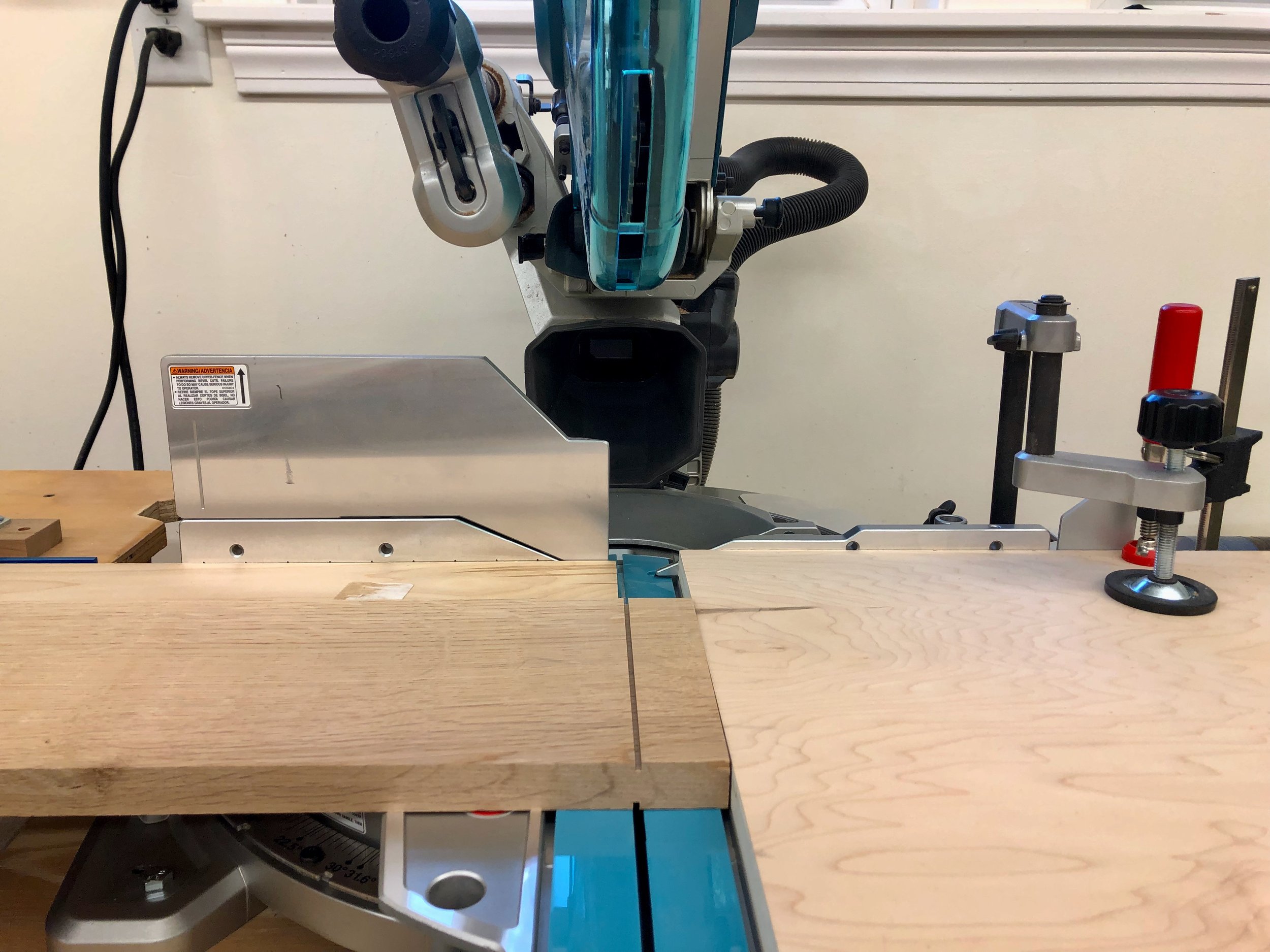
Making uniform tenon shoulders at the sliding miter saw
The rest of the tenon “cheek” was made by sequentially moving the board 1/8 inch “backwards” and cutting away another kerf’s worth, etc. The bandsaw also works well here for smaller pieces but these big guys are easier to handle prone. The tops and bottoms of the tenons were then cut off using a combination of hand saw for the cross-cut and a band saw to rip the final dimension, a 4 inch tenon on 6 1/2 inch rails.
Four tenoned bottom rails
If the job is done right, coming off of the saw the tenons should be just fatter than their leg sockets, and they were. These were then trimmed with a shoulder plane and chisel until a firm fit in a fully seated joint was achieved.
Next, I took a deeper dive into the published plans and decided to make some changes. For some reason, the plans called for six taller, so-called “outer” stiles to mate with all of the legs, on to which the upper rails would be attached. All of the seven remaining “inner” stiles would then sit in between the upper and lower rails. Hmmm … having the upper and lower rails attached at different points seemed like an odd feature to me and one that might actually make for a weaker structure. Sure enough, examining the photo of an actual antique piece (above) and trying to glimpse these joints in pics available on internet auction sites and Pinterest revealed the “original” joint repertoire to be simpler. Back in the day, the upper rails, like the lower rails, attached directly to the leg pieces. All of the thirteen stiles were the same size and rode in between these rails, visually elegant and strong. Unsure why the published plan would deviate from authenticity, and even though it meant refashioning some already dimensioned boards, this was the way to go. Now back on track, the new upper rails were dimensioned with 3/4 inch tenons on the ends and the leg and rail structure was assembled (dry) to check for fit and to mark the next cuts.

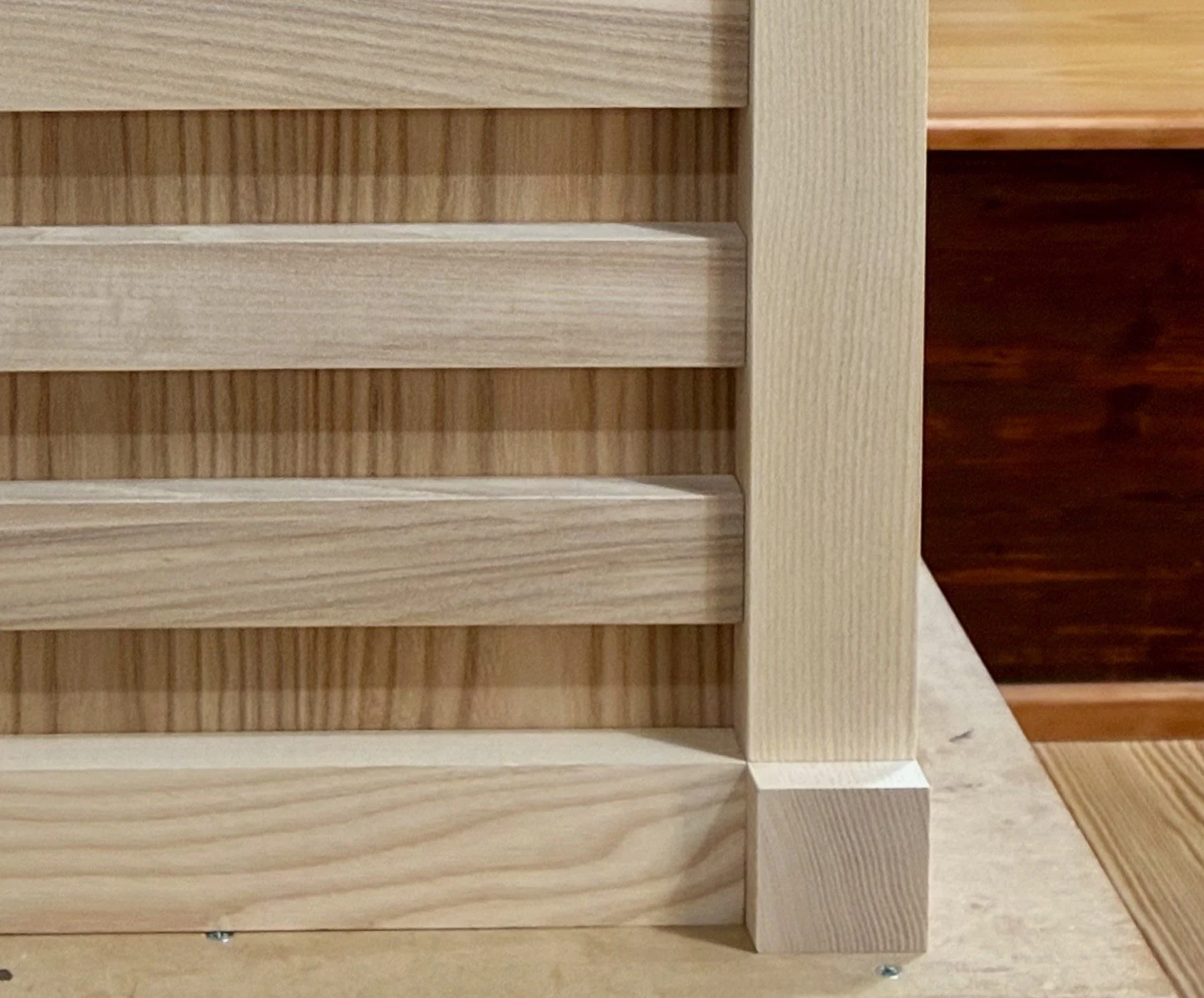
Dry-fitted leg and rail structure
Everything seemed to fit together properly (with barely enough room to maneuver in the bench room once assembled). Prior to disassembly, all of the edges to be grooved for housing panels were marked appropriately so that no mistakes would be made at the saw.
Job 2: Stiles
Next the thirteen stile parts were dimensioned to proper thickness, width and length before conducting the “value addition” steps associated with joinery. First, using a dado blade at the table saw, a 1/2 in. wide tongue, 3/4 in. deep was created along one edge of the six stiles that connect to the legs. These were then cleaned-up and tested for fit. The table saw and fence were then set up to cut 1/4 in. wide dados at 1/2 in. depth. All of the stiles and some of the rail edges would receive a full length dadoed groove that would eventually receive the panels. A few cuts and adjustments were made on a test piece and then, once satisfied with the result, all of the parts were run through the saw in succession.
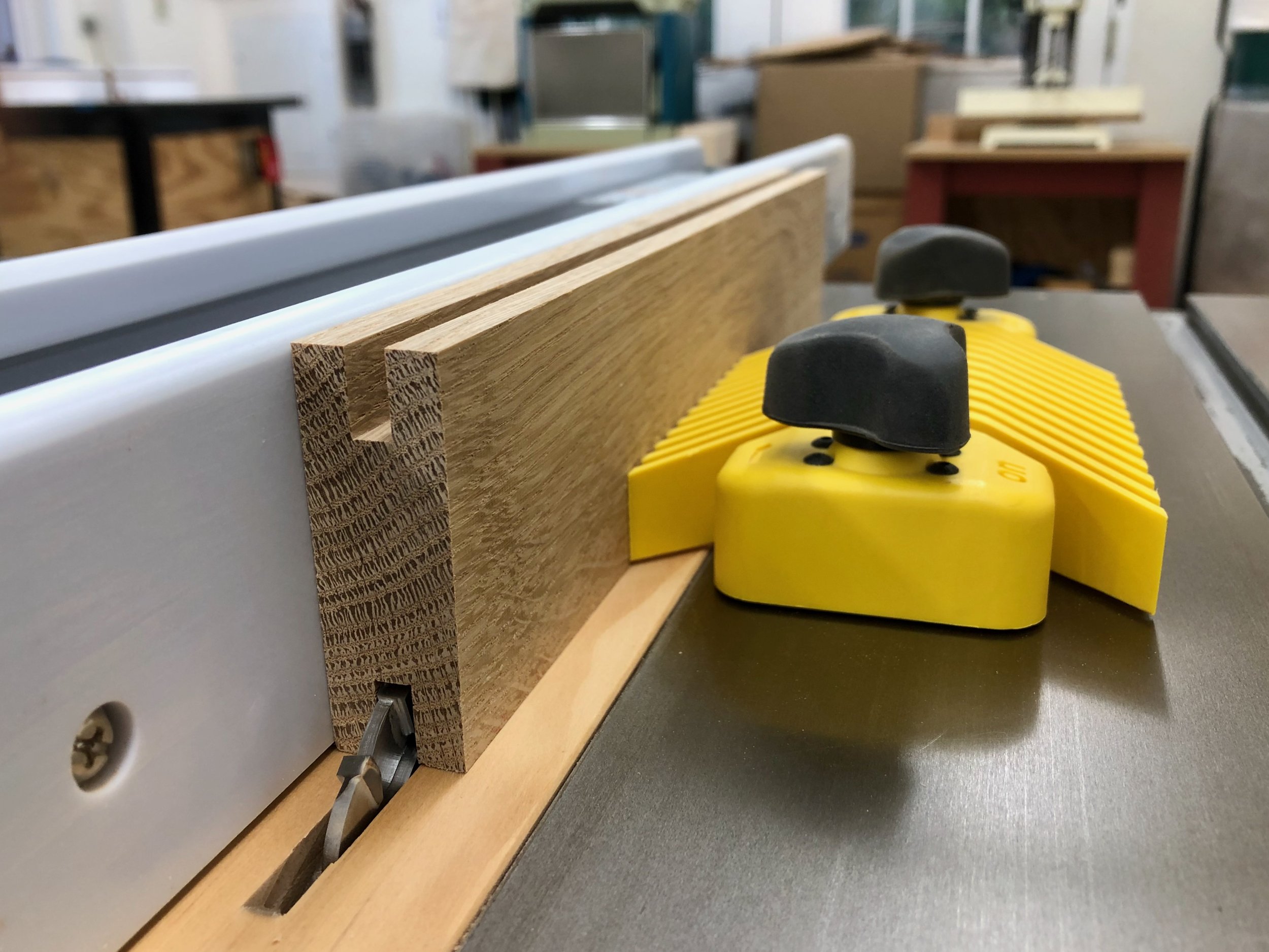
Cutting grooves in a stile
This operation completed the rail pieces, however, the stiles would still need to have tenons fashioned along their tops and bottoms to ride within the grooved rails. These were also fabricated at the table saw using a wider dado blade, the cross-cut sled and a stop block.
Cutting tenons on a stile
After a bit of clean-up with chisel and shoulder plane a dry fit of the 24 frame parts confirmed that all was on track. This also allowed for final measurement of the panel dimensions.

Framework fit together
Job 3: Panels
I’ll just say it: making panels is an enterprise that seems to take longer than it should. To be sure, there’s a beautiful payoff in the end, but one still has to be in the proper mood for panel-making if the exercise is to be enjoyed. So after cleaning the shop, sharpening some chisels and re-surveying the remaining boards I managed to muster enthusiasm for this next task. To start, you cut the lightly thickness-planed 4/4 boards to rough length and width at the miter and table saws, respectively. You then re-saw them along their narrow dimension into two pieces at the band saw, and finally thickness plane these thinner boards to a uniform 3/8 in. depth. This creates a bunch of panel halves, twenty to be exact. To construct the panels, the “interior” edge of each re-sawn pair is squared-up at the jointer and then, after aligning the grain in a book match orientation, they are glued together and clamped; two at a time given limitations in both clamps and space.
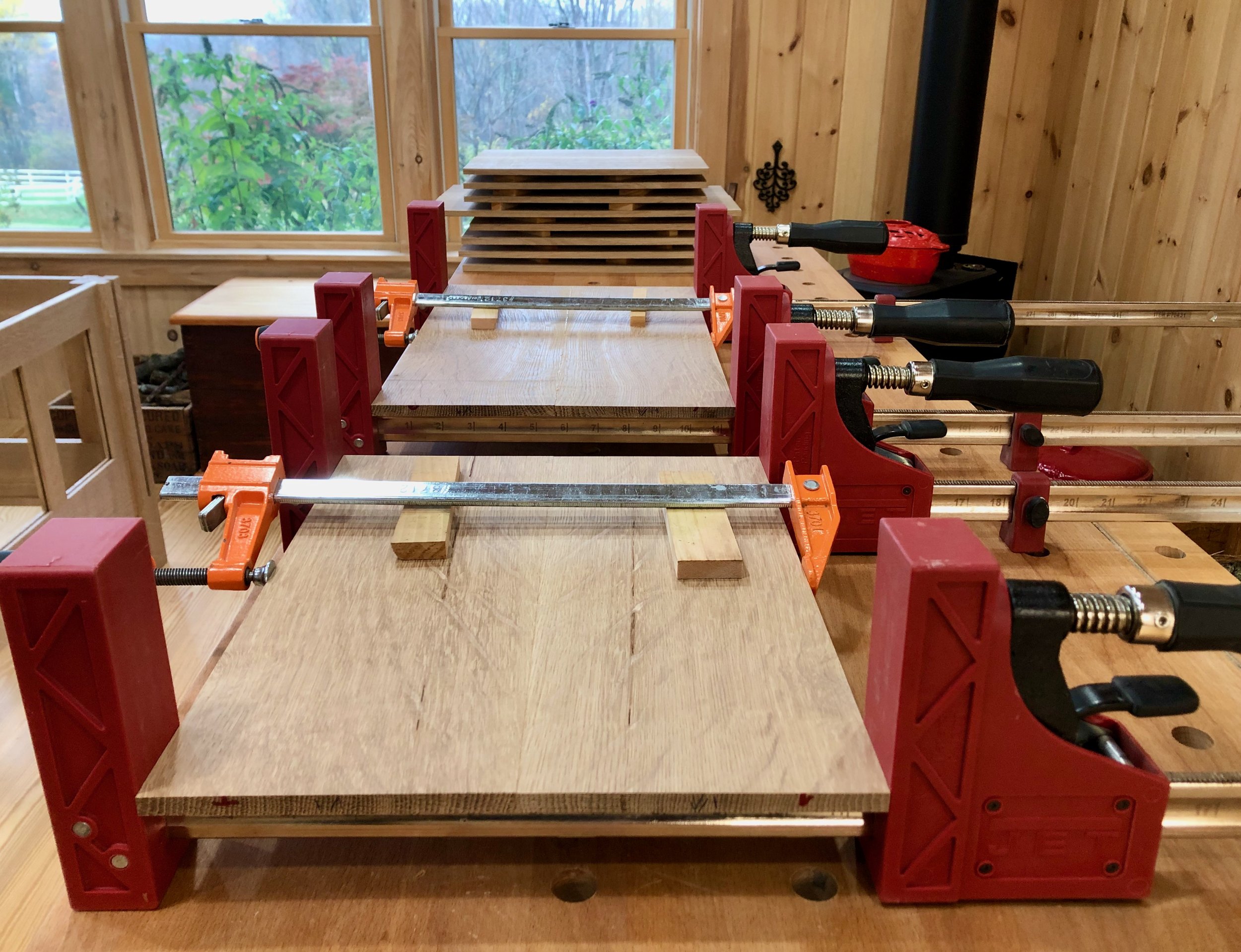
Panels in production
Once the glue has dried the rough rectangles are smoothed with a card scraper and orbital sander (150 grit) and then cut to their ultimate width and length dimensions, again at the table and miter saws. For appearances sake I made sure that the glue seam exactly bisects the finished parts. At this point, and by design, the boards are still too thick to enter their grooves. To achieve a fit all of the edges (n = 40) need to be beveled, thereby creating a “paneled” feature on the interior face. For this I used the table saw panelling jig made a while back during the candle box Project to create 1 inch wide tapers along all sides sufficient to provide a snug fit into the grooved stiles and rails.

Panelling the panels at the table saw
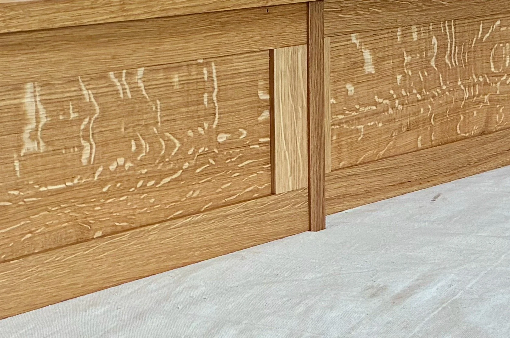
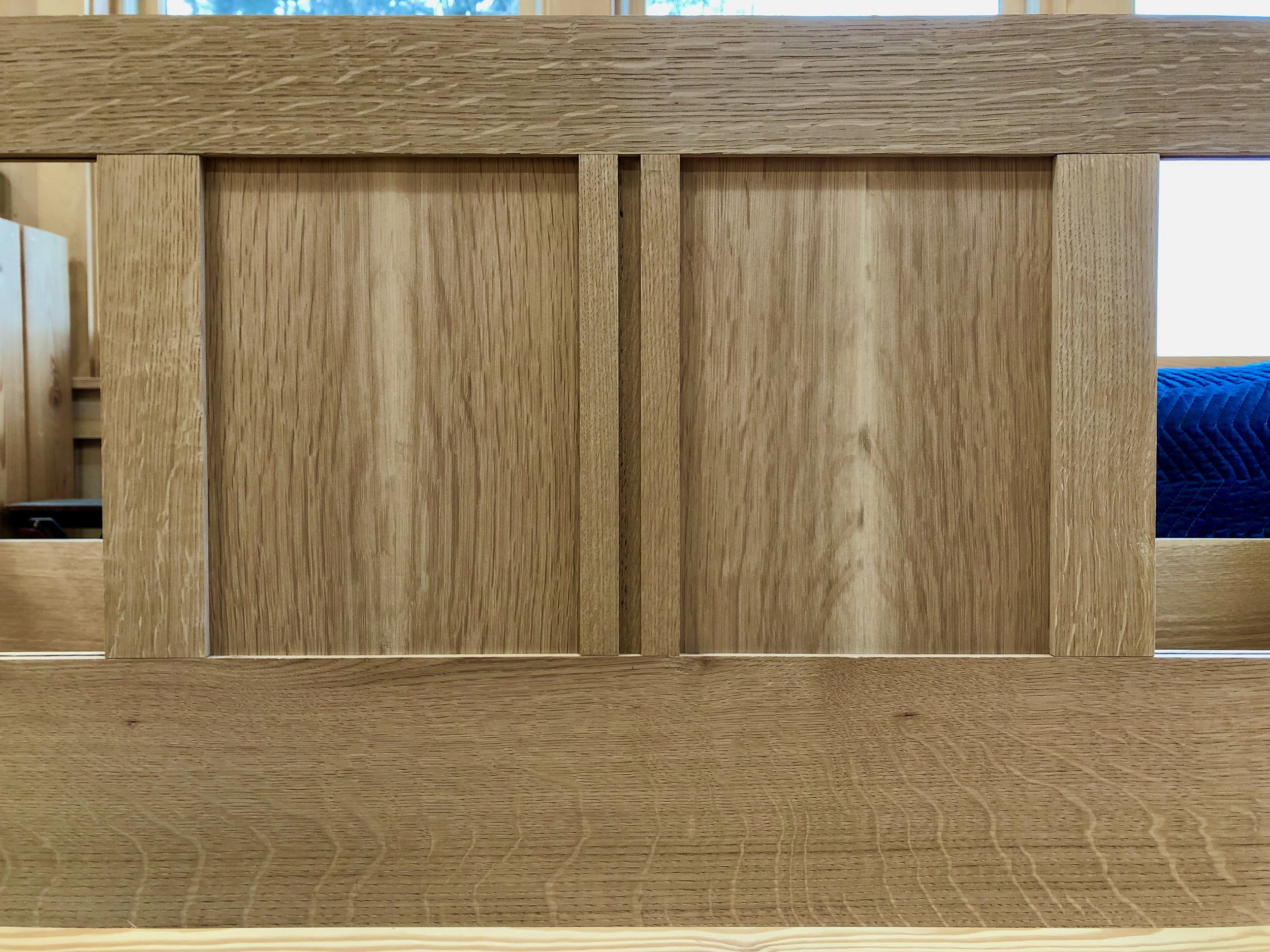
The newly cut perimeters were then smoothed lightly with a card scraper, sorted for their position within the framework and nestled into place. As each individual panel exhibits its own grain & ray “personality”, there is some artistry here in their placement with respect to patterns present on the neighboring rails and panels. Once upholstered, the un-paneled sides of the panels are the only ones that show, and my desire was to frame each of these to their best effect. The “interior” sides have their own uneven beauty, too, revealed during the dry fit.
Dry fit panels in frame
Job 4: Details
Almost ready for the glue-up, but first there are a couple small details to attend. The stiles need to be planed flush with the rails and then labeled for their position during assembly. This was done individually by first identifying any “proud” edges on the end of a stile-rail joint, dismantling that part from the frame, diagnosing the wood grain direction and carefully hand planing away the excess until it tests “flush enough”. The trick is to not plane too deep here as a post-assembly sanding job can accomplish a final smoothing of these joints.
Next, the center stile along the back needed to be grooved to accept a corbel that will support the wrap-around arms. A 1/2 in. wide dado was cut 1/4 of an inch deep into the center of the stile at the table saw. This joint is not mentioned in the plans so I assumed it would be like those that mount the other corbels to the legs. However, I was reluctant to make a groove the full-length of the corbel, and in the process weaken the associated rail members with a cross-cut dado, so I decided to leave the top and bottom rail alone with the intention to use screws from the inside face to further secure the corbel during assembly. This is certainly a departure from authenticity, but an invisible one at least.
Grooved center stile in place
The front rail also needed to be beveled along the top edge so as not to irritate the legs of those seated above. This was accomplished at the table saw, applying an 18 degree angle to the blade and beginning the cut 3/8 in. into the thickness dimension. The rough edge was easily smoothed by hand using a card scraper.

Beveled front rail
Finally, those corner seams about the quadralinear legs needed to be dealt with. Recall, the formation of these pieces left a noticeable gap along many of the edges. I had been puzzling on the best way to remedy this situation when my furniture maker son, Andrew, suggested using a burnisher (the tool otherwise used to fold a cutting edge onto my card scraper) to gently crimp the gap shut. He then proceeded to show me how easy this was to accomplish. The result is a smoothly rounded over edge on all of the legs!

Seamless leg corner and burnisher
Assembly
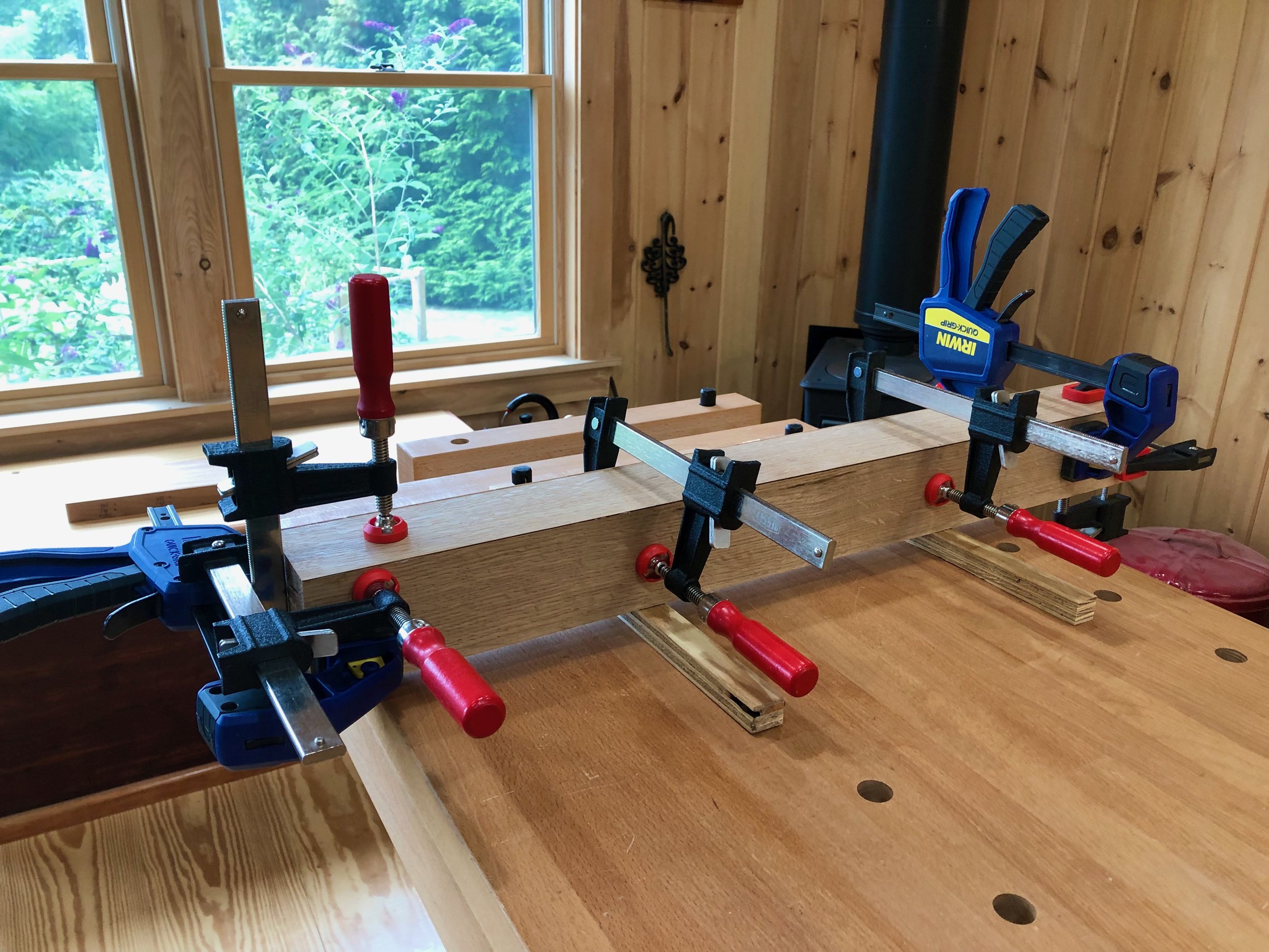
With all of the jobs complete, it was time to glue the frame together. This meant completely disassembling the dry-fit structure and amassing my collection of long clamps for duty. I started with the Left side sub-assembly. These nine parts were put together with ample glue, clamped tight & square and left standing upright. Four hours later, the clamps were liberated and the process was repeated for the Right side, being sure that everything matched exactly in a mirrored sense. The rail-stile joints were then lightly sanded flush with an orbital sander using 150 grit.
Having completed the sides the final step was to join them together with the Front and Back rails. Of course, this included the remaining stiles and panels where there were a lot of wooden junctions to get right. To begin, the two bottom rails were glued to the sides, creating a free-standing rectangle. The back center stile was then affixed, followed by the two flanking panels, and, from there, assembly proceeded outward in both directions. The stiles were fastened with glue, whereas the panels were tapped-in dry. Gratifyingly, following another such iteration, there remained sufficient space to slot panel nos. 1 and 6 into place. After checking that the stiles were all mounted squarely, the top rail was then tapped down into place. Various pipe and bar clamps were applied as the structure was checked and adjusted for squareness one final time before lockdown. Big job!
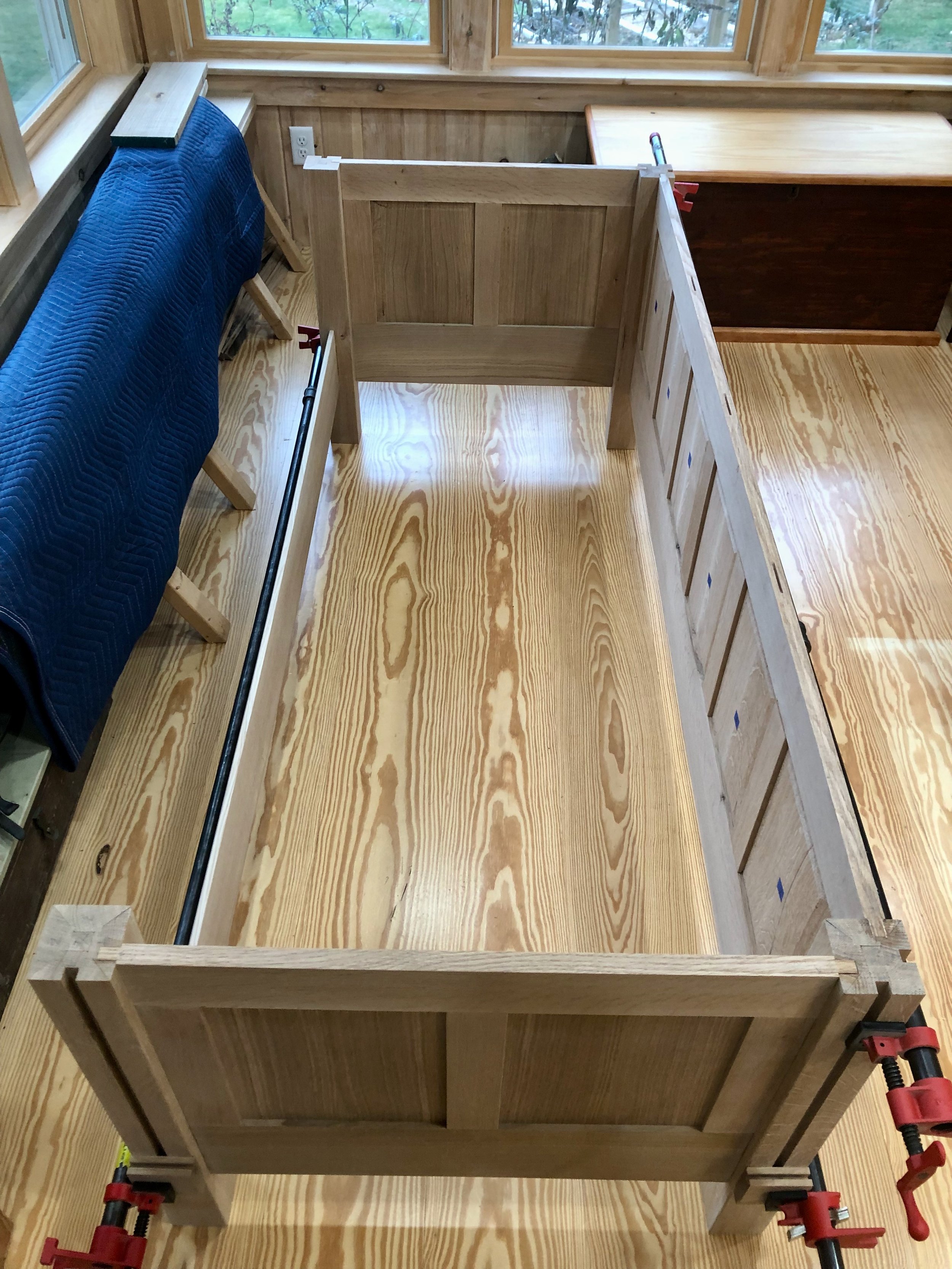
Glueing-up the frame
Finishing touch
A defining feature of Arts and Crafts furniture is the pegged tenon joint. Adding equal parts strength and character, this element was highlighted by the Stickleys perhaps more than any other maker. The pegs (dowels) in this piece secure the front and back rails to the legs and are shaved flush with the surface once installed. I chose 1/2 inch diameter round dowels for this task, which first needed to be fashioned in the shop.
In the mature craft of woodworking there is at least one tool for every job, and the tool for creating wooden dowels is as simple as they come. A round hole cut neatly into a metal plate is the implement used for dowel-making; that and a hammer. The dowel material comes from a straight-grained, knot-free white oak scrap. This piece was first cut to rough dimensions on the table saw (9/16 x 9/16 x 24 inches) after which the edges were further relieved by shaving with a knife. The resulting irregular-shaped rod was cross-cut into 2.5 inch segments, trimmed further along the exterior with a block plane and then pounded through the circular opening of the “tool” to produce perfectly sized cylindrical dowels. While the act is violent, the result is beautifully Euclidian. Using a pencil sharpener, the penetrating end of each dowel was tapered slightly before use.

Pounding out the pegs
To peg the tenons, two 1/2 inch dia. holes were drilled to a depth of 2 inches at each of the rail-leg joints. I used a hand drill and shop-made jig to keep the holes uniformly positioned and straight. A glue-coated dowel was then tapped firmly into each opening and, once dried, the protruding end was sawn off using a Japanese flush cut saw. Finally, the rough surface was smoothed with a block plane.

Pegged rail joint
At last the frame is done and this brings the Project to a natural pause. Left to be completed are the arms and their support structure, the upholstery and the finish. Well on our way!


The Railing

I like my neck. Sure, it’s developing that middle aged turkey “thing” but I’m for preserving it all the same. For that matter, I’m rather fond of my wrists and pelvis too, but you wouldn’t know it if you saw me slipping and sliding down the path to the workshop last winter. That’s all about to change with the creation of a new railing.
Background
The door to the Red Top Workshop sits maybe 60 feet beyond the steps from our kitchen deck but there is a 6 foot elevation drop over that span, the final 4 feet of descent navigated along a 20 foot long, stepped pathway put in by the former owner. Nice little treacherous walk. In the winter, ice will glaze the granite landing treads at every opportunity and also form a rather slick rink atop the sloping pavered sections in between. I’ve tried salt, sand and chipping with a pick but it is difficult to keep this stretch clean and safe over a New England winter. After a few painful spills I resorted to the use of boot crampons and a walking stick for assistance with traction and balance. The problem is that I am rarely walking that path to the shop empty-handed. Firewood, furniture lumber, coffee mugs; these things don’t get down there by themselves. What I needed was a sturdy anchor to the ground, a railing, to support my frame and cargo during transit. Pretty sure my insurance company would agree.
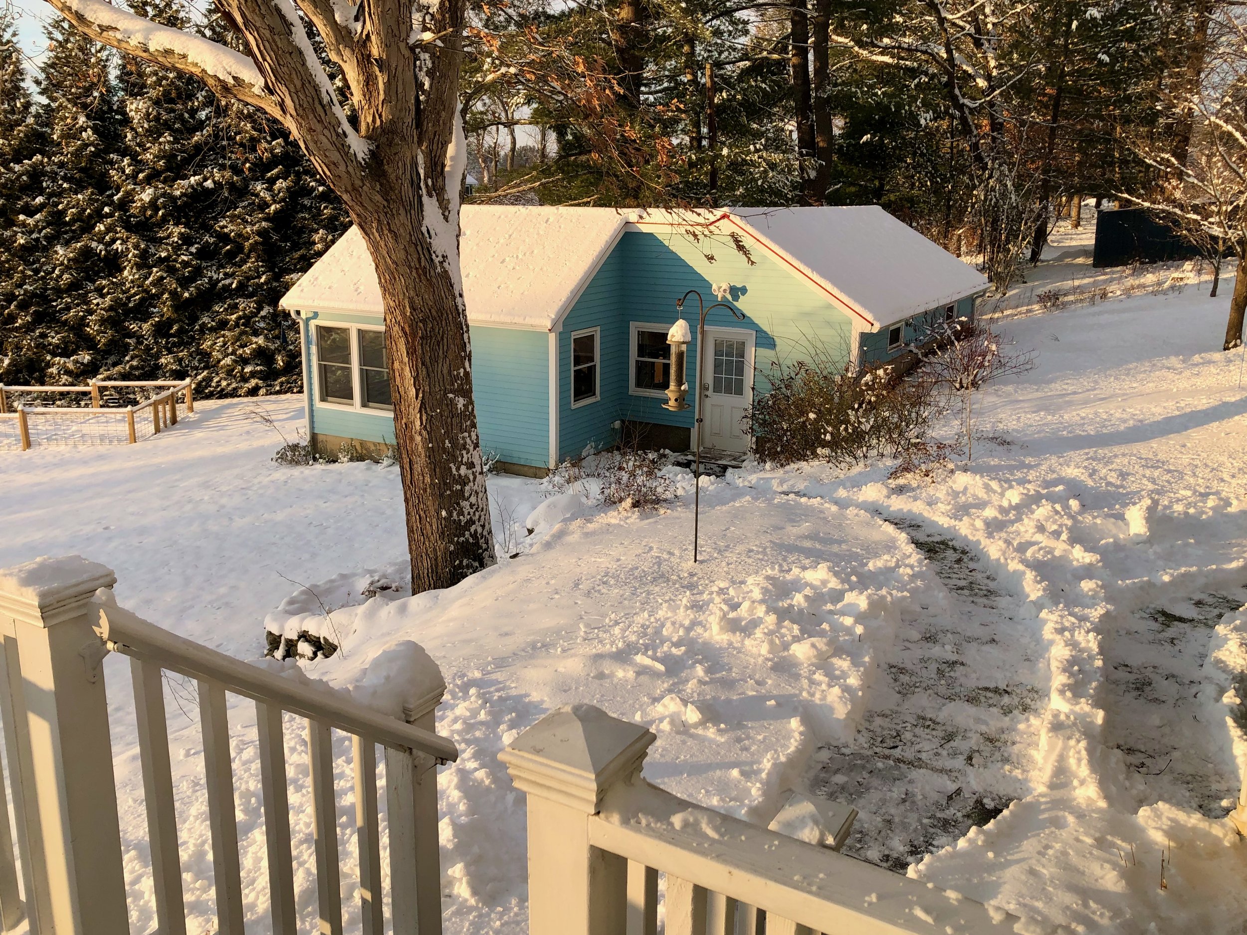
The winter commute
Design
The plan began, as most plans do, by first ruling things out. I neither wanted nor required a typical split rail-type fence for this short span of walkway; it would be too massive for the task. A black iron porch-type railing would work, I suppose, but that would seem out of place in the understory bird cover that I was also trying to establish here; like an artifact overgrown by jungle. What I desired was a right-sized, simple handrail support that would blend with the setting. It needed to be wooden, of course, and not shy about declaring its function, kinda like Craftsman furniture (wink).
A rough plan meeting these criteria was created on graph paper to verify feasibility and “look”. I decided that the railing should be perpendicular to the posts and not sloped to match the terrain. This might take it out of OSHA compliance but I feel it makes the railing more “fence-like” and naturally prompts a re-grip at each granite lander.
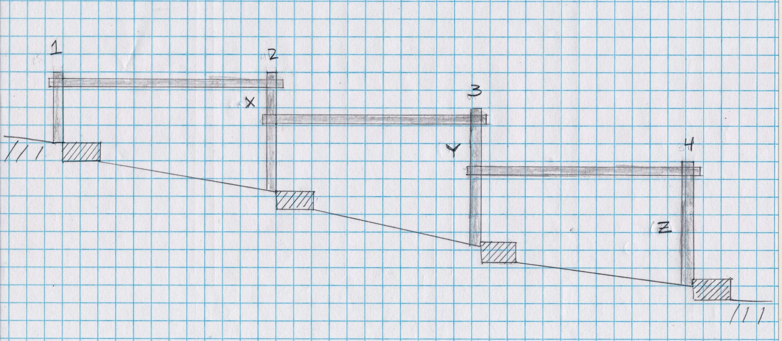
The railing plan
Materials
It turns out that there are very few non-metallic fence materials to choose from at the typical Lumber/Box store. Avoiding split rail pieces and those cumbersome 4x4s I settled on some landscape timbers made from pressure treated yellow pine. These are typically found stacked together on the ground and used as borders but, lumber-wise, I could imagine them to be “live edge” 3x4 inch fence stock. The remaining materials were easy. I would use quick setting concrete for the footings and galvanized carriage bolts to join the members together. Material costs came in just under $100; about the price of an office visit and X-rays, deductible met.

Landscape timbers in lock-down to combat warp prior to construction.
Construction
Structures such as these are made in cooperation with their environment and, as such, ground preparation, rail fabrication and installation would proceed as a loosely-choreographed dance. This adds to the excitement, and if you’ve ever done a garden project you’ll know what I mean.

The un-railed path
While the basic design was set, I still wanted to test some joint options before deciding on the post orientation (i.e., in which direction should the flat sides point?). Detail-wise, I planned to use a cross-lap joint to marry the railings with the posts. This would keep the profile slim and make it all look more purpose-built. That left me with four permutations for how the edges should meet depending on whether the flat or round edge of the post mates with the flat or round rail edge. To decide, I mocked-up the favored option (flat post on flat rail) and then, given the amount of work it took to build this one, assured myself that it was the best and no others need be sampled. The “flat-on-flat” variant would face the flat sides toward the walkway and furnish the more comfortable hand hold, so there’s that too.
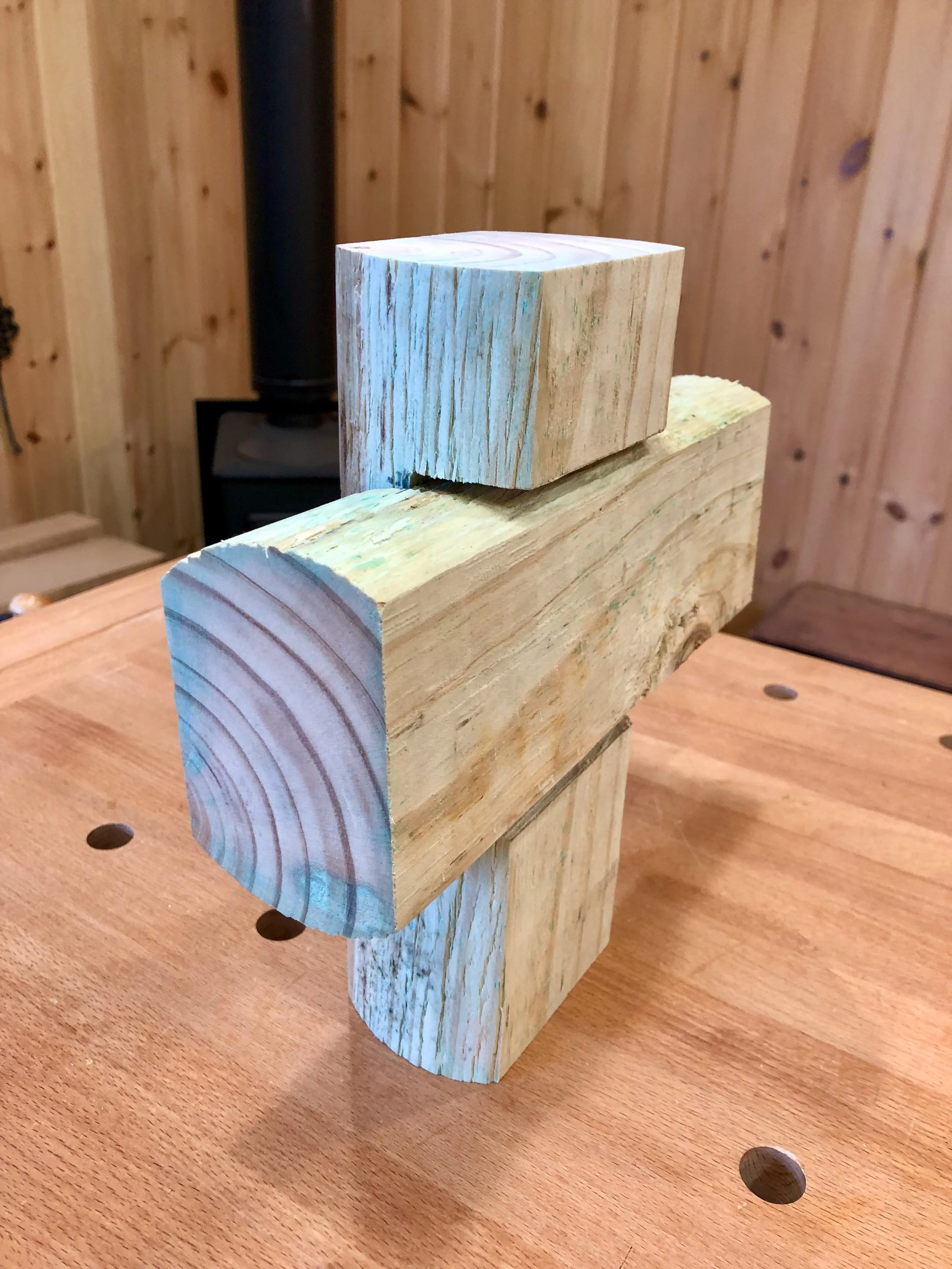
Flat on Flat cross-lap joint
The joint was built by making two boundary-defining cuts with the hand saw (1 1/4 in. deep, 4 inches apart) and then chiseling out the interior waste to create a “slot”. This slot was then overlapped with a second such slot to fashion the cross-lapped joint. It was pretty simple work and I think the damp “wonder wood” actually helped with the chiseling step. However, it took a lot of whacks to make a joint, and convinced me that, in addition to the railing cuts, the 6 slots in the posts would also need to be fabricated in the shop prior to installation to keep the chisel pounding from dislodging everything in the ground. Alternate methods for cutting the posts using a router or table saw were vetoed in favor of manual labor, which just felt right.
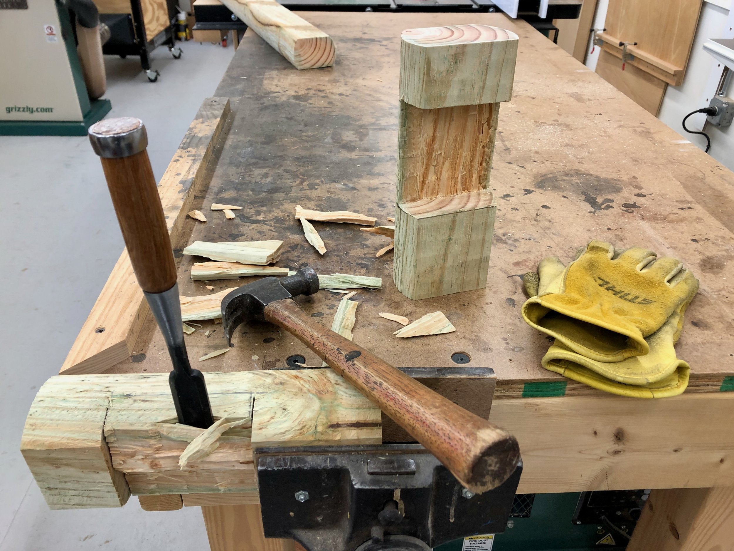
Chiseling slots in the test joint
Having decided on this method of construction meant I now needed to re-formulate my installation plan. My original vision of cementing all of the posts in place and then cutting-out the railing slots no longer applied. And, while it would be bit more complicated than just sequentially digging/inserting/fastening from one end to the other, that’s basically how the new plan goes. Here are the constants and variables in play. Regardless of their length, all slots on the railings would be created 2 inches in from the ends, likewise, the posts to receive these railings would be slotted 2 inches below their tops. Further, the uphill end of all railings would start at 22 inches above grade. These constants come from the design and keep things simple, trim and uniform. The variables come from the environment and are largely due to the inconsistent drop in elevation between the granite landings. We don’t need to measure this decline, simply accommodate it during construction. In practice this drop determines the position of those niggling second cuts on posts 2 & 3 and height of the cut on post 4, depicted as segments X, Y, Z on the plan (above). A persistent bend in the pathway and non-uniform spacing of the granite blocks contribute the final variables.
Following a few last minute measurements it was time to dig the first hole. I started up top with the shortest post. The plan was to bury each post about 2 feet into the ground and tight to the existing walkway. Down there they would sit on a bed of gravel and be anchored by a concrete surround. A post hole digger did a good job excavating the 10 inch dia. cylindrical cavities, and since the ground consisted of fill dirt I did not have to fight with New England rock.
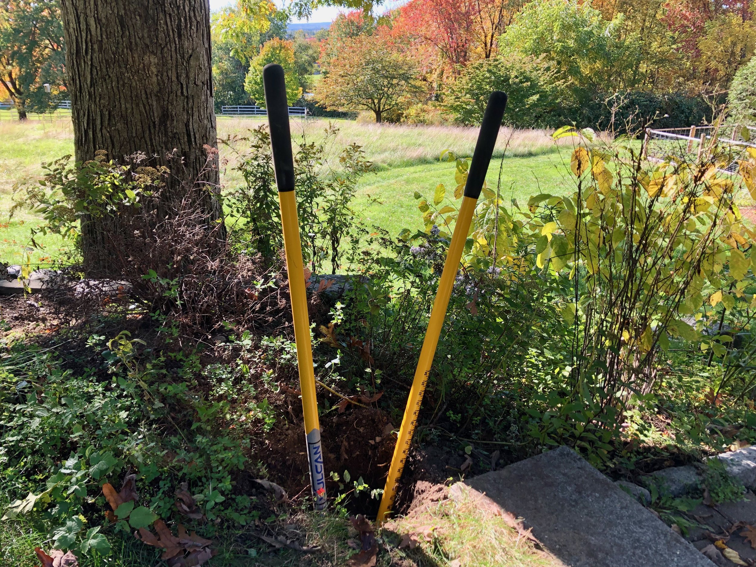
Digging the first hole
A handy jig was made to assist with mounting the posts. This consisted of a few 2x4s put together in a manner to hold a short section of railing 22 inches above the granite step. Once the bottom of the post was trimmed to length, inserted into the hole and tamped into the gravel bed it could then be held at the proper height by inserting the rail section of the jig into the joint slot. Following instructions written on the fast setting concrete bag some water was then poured into the hole followed by half-filling with concrete powder. At this point the post, held by the jig, was re-leveled on all sides. The hole was then nearly filled with powder and more water poured on top. After a few minutes of soaking, the concrete on top was the consistency of pottery clay and could be tapered with a trowel to shed rain water away from the post. Following a final level check this was then left to cure while the next hole was dug.

First post in place, held in position by the jig
Getting the second post in the ground and the first railing attached to it would complete a “section” and validate the procedure to be used hereon. I’ll describe that process so that afterwards we can fast-forward to the finale.
Hole no. 2 was dug to 24 inches and the jig put in place so that a measurement from the bottom of the hole to the stub rail could be made. This distance determined the position of the first slot on post #2. That slot was cut-out in the workshop, as well as a slot on the end of rail #1. A pilot hole for the first carriage bolt was also drilled into the rail. Next, the post was put back in the hole, leveled and mounted to the jig. Rail #1 was also temporarily installed onto post #1 by completing the drilled pilot hole and sliding a carriage bolt through it. This “dry fit” would allow me to mark the position of the final two slots. Upon leveling the rail and bringing it alongside post #2 I could pencil the intersection on both members, defining the areas to be cut for the joint. (Hope that was clear.) Removal of the temporarily mounted rail and post allowed for chopping the joint slots in the workshop and then cutting the members to final length. Installation was simply a repeat of the dry fit exercise, only with wet concrete thrown in. Worked well!

Dressing concrete upon completion of the first section
The second and third sections were completed in a like manner over the next couple of days. At some point I realized that sawing a relief cut mid way across the 4 inch joint slot made the subsequent chiseling step much easier - enjoyable actually. Always learn!
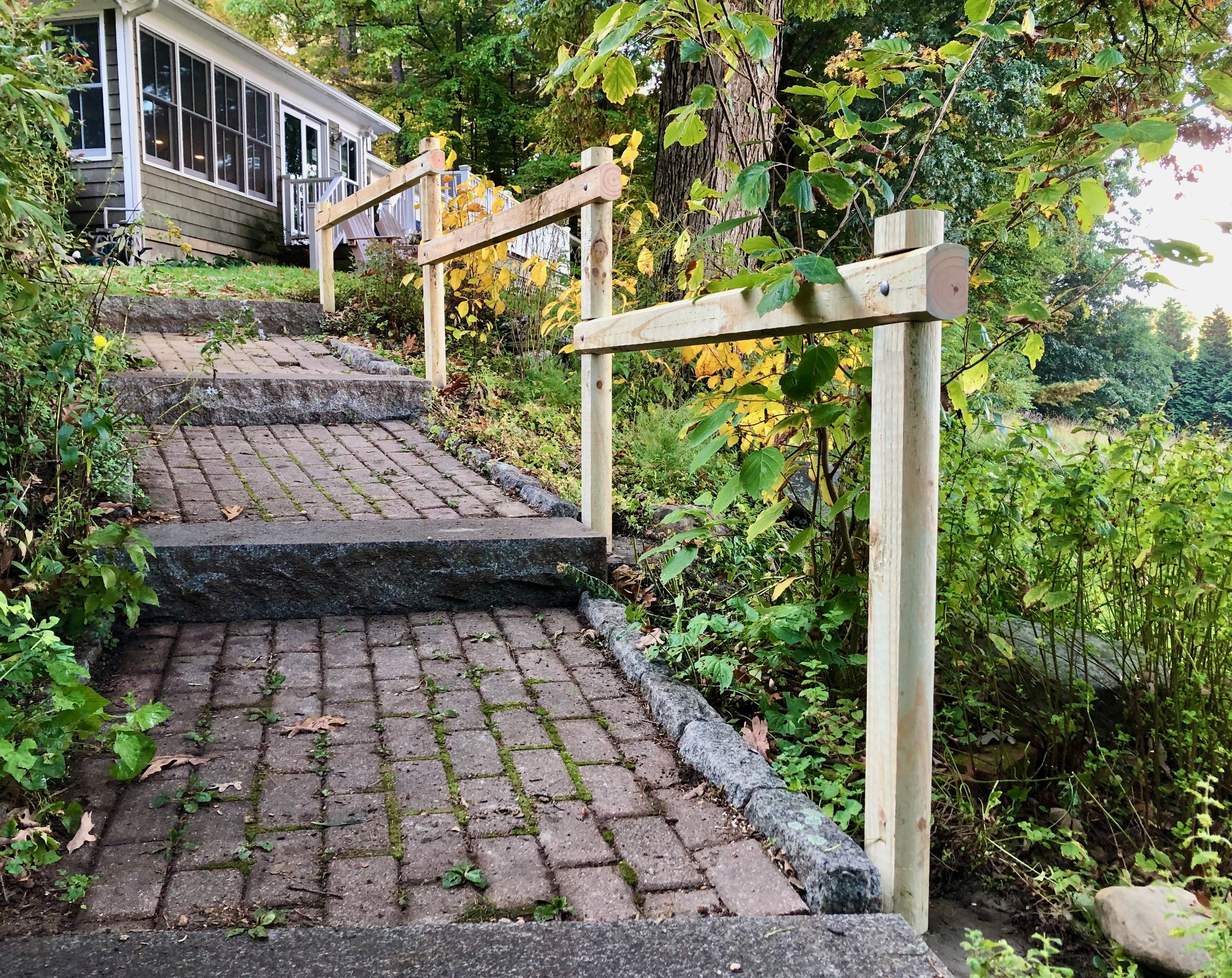
The newly-railed path
These garden Projects are a reminder that it is fun to get out the heavy tools on occasion. They are a chance to not sweat the final 1/32nd of every inch and still build something solid & useful. Assuming those posts stay put when the ground freezes I think this railing will enhance both the beauty and safety of the workshop path for many years to come.


No. 220: the legs

Prelude: The next few installments will describe the creation of a No. 220 Prairie Settle. Following a brief description of background and preparation this first episode focuses on construction of the leg components.
The allure of Craftsman furniture, regarded as America’s first true furniture form (sorry Shakers), comes from the simplicity of design and material. Graced with very few ornamental detours, the admirer is forced to recognize and then appreciate the form, joinery, wood and finish that, when executed properly, create a beautiful four-part harmony. I love the Craftsman aesthetic and have made a few pieces inspired by that style, as well as some related mission items. In most cases I have either reverse-engineered the plan from a 100-year old picture or created my own design using dimensions and joinery consistent with the style. On my last Project I stuck pretty close to the original published plan and found it a surprisingly absorbing challenge to re-create an antique. I’d like to do the same for the venerable No. 220 settle first made in 1912 by Leopold & John George Stickley, and in this endeavor I am helped enormously by the work of Robert W. Lang.
Robert Lang is a very talented woodworker, magazine editor and author who is also regarded as a specialist in Craftsman furniture. In addition, he manages an incredibly informative website. His latest passion seems to be the drawing program SketchUp which he uses to re-create plans for authentic furniture pieces. In 2013 several of his earlier books were combined into the hefty, Great Book of Shop Drawings for Craftsman Furniture. This masterpiece, since re-issued in hardcover, contains his painstakingly derived plans for many Stickley and related furniture pieces, and among these is the No. 220 settle. I don’t believe I’d have the confidence to tackle this large Project without these plans. Thanks Robert.

No. 220 plan
from: Lang, R.W. Great Book of Shop Drawings for Craftsman Furniture, Revised & Expanded Second Edition Fox Chapel, 2017.
Design
A fair description of early Craftsman settle designs might be ‘four posts, modified appropriately to accommodate the human derriere’. Endearing, yet visually crude by today’s standards, the settle was intended to provide cozy comfort to those who “settled” within its confines in an otherwise drafty room of old.
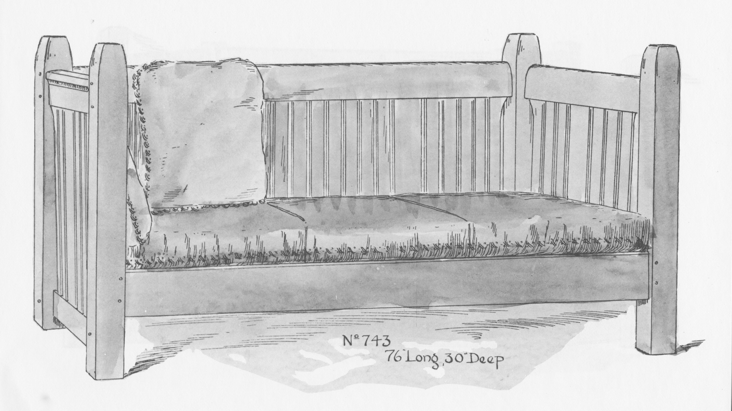
(example) No. 743 Settle
from: L. & J.G. Stickley, Onondaga Shops Salesman’s Catalog (1906), reprinted in: Early L. & J.G. Stickley Furniture: From Onondaga Shops to Handcraft, Davidoff, D.A. and Zarrow, R.L. Ed., Dover, 1992, p.61.
Later versions tended to separate the height of the back from the height of the side “arms”, making something that more resembles the modern sofa.
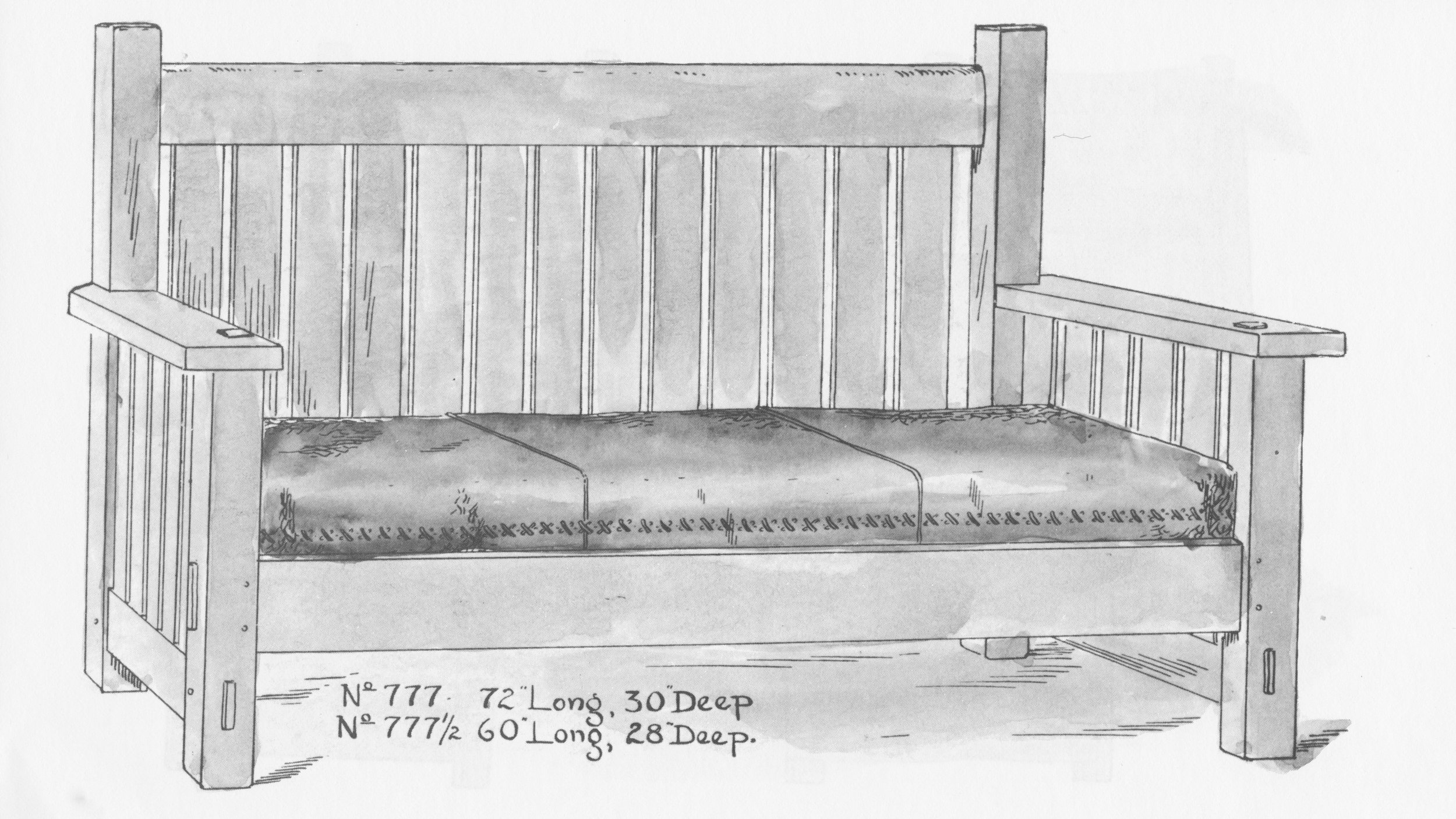
(example) No. 777 Settle
from: Early L. & J.G. Stickley Furniture, p. 77.
No. 220’s genius was to once again align the back with the arms, but this time at arm’s height, evoking the expansive Prairie sensation. The leg posts are still present to anchor the settle form, but with curvaceous corbels to support the massive arms they are no longer the primary feature.

No. 220 Settle sketch
from: Great Book, p. 150.
Materials
Although the Stickley’s offered some early pieces in a variety of woods (mahogany, chestnut, maple), white oak, quarter sawn at the mill, became the most prevalent wood used for Craftsman furniture. This abundant hardwood was the perfect material for the construction of solid furniture. Due to the orientation of the annular rings, quarter sawn lumber is the most stable form with regard to seasonal movement, and when white oak (Quercus alba) is cut in this manner it reveals the pronounced medullary rays found in this species to create a striking grain figure. Amongst all of the diagrams of quarter sawn lumber to be found in the woodworking literature, I prefer Gustav Stickley’s.

Quarter sawn lumber
Stickley, G. The Craftsman, VIII, 4, 1905, p. 109
I needed a few different dimensions for this Project and spent 2 hours picking through the quarter sawn white oak stacks for the right pieces at my favorite yard, Highland Hardwoods; 76 board-feet in all.

White oak stock
(note medullary rays evident in the center, S3S boards)
Dimensioning
While Stickley furniture legs might appear to be simple posts, simple they are not. The desire to exhibit quarter sawn grain on all four faces means they have to be specially constructed, or else gimmicked with the use of veneer. Gustav was not above using veneer for some pieces, but L. & J.G. devised a clever method to create a leg post out of four boards, fashioned in an identical manner on their factory’s machines. They even describe this innovation in their catalog, including a claim of practical indestructibility!

The Work of L & J.G. Stickley, Fayetteville, NY (c. 1914).
reproduced from: Stickley Craftsman Furniture Catalogs: Unabridged Reprints of Two Mission Furniture Catalogs, Dover, New York (1979).
Making these so-called “quadralinear” legs begins by jointing the 5/4 rough boards square, thickness planning to 1 1/8 in. and then ripping to 3 in. widths and finally chopping to 30 in. lengths. To shape the joint, some modern day woodworkers have adopted special router bits, but I wanted to match the L. & J.G. parts. I do not have a shaper like they would have used, but Lang describes a method to make this exact leg with 4 cuts (per board) at the table saw. Details of this process are given in the Great Book, referenced above. Briefly, one creates two shallow grooves along the inside face of each leg board using a dado blade and then the portions exterior to the grooves are removed with a conventional table saw blade angled at 45 degrees. All four cuts are unique and it takes a bit of futzing to get it right. To keep things uniform it is best to make each cut 16-times in succession (i.e., once per board), and then set-up the fence/blade to make the next 16 cuts, etc. Sixty-four cuts later, all leg parts should be identical to one another and hopefully correct. Of course, you won’t know how correct until you’ve completed the 49th cut and by then you might as well just keep on cutting. I’ll use the pictures below to walk you through it.

Step 1.
Planning the cuts with a marked reference board. (Note: the 45 degree cuts meet the groove edges at different corners)
Step 2.
Cut two 1/4 in. x 1/4 in. grooves on the undersides.
Step 3.
Make the initial angle cut with “show face” down and fence to the left of the left-tilting blade (re-enacted).

Step 4.
Make the final cut using a home made jig to stabilize the piece; “show face” up, fence on the right. (off-cut removed for clarity)

Milled leg parts ready for glue-up.
It took half of a day to complete but went rather smoothly. I think the home made jig, invented to shepherd the boards through their final cut, was key. During this operation the piece has a chance to wobble while riding the table on a narrow central spine and with only a thin mitered edge touching the fence. The flat surfaces of the jig riding against the fence ensure that the piece is cut nice and straight (while also keeping your hands clear of the action). The corner seams of the dry-fit legs are still not perfect, each leg exhibiting one or two thin gaps down their length, but I think when glued-up and sanded down they will look just fine. Before the glue-up I wanted to make some square “rods” to fill the central cavity within the legs. I found it was a simple task to glue together two of the triangular shaped off-cuts from step 4. to form a square-ish piece of exact length that could then be trimmed to 3/4 x 3/4 in. size on the table saw. These were tucked into the voids during the glue-up which went smoothly using F-clamps. I would need to blunt the sharp edges and fill some hairline cracks at the seams but this would best be done closer to the finishing steps.
5 boards make 1 leg.
Next, the legs were trimmed to their final length at the miter saw and then a positional assignment was given to each member (i.e., Left/Front, etc). The bottom rails, panel frames and corbels all need their joint sockets cut-out at this point. The cut patterns come in pairs (2 front and 2 back) but since those on the left are the mirror image of those on the right, all four posts are distinct and care must be exercised not to make an errant cut along the way. Prior to the shop work, I took the time to sketch each leg face on paper, indicating the cut positions and dimensions with the hope that this exercise, replete with erasures, would help things go smoother in the event.
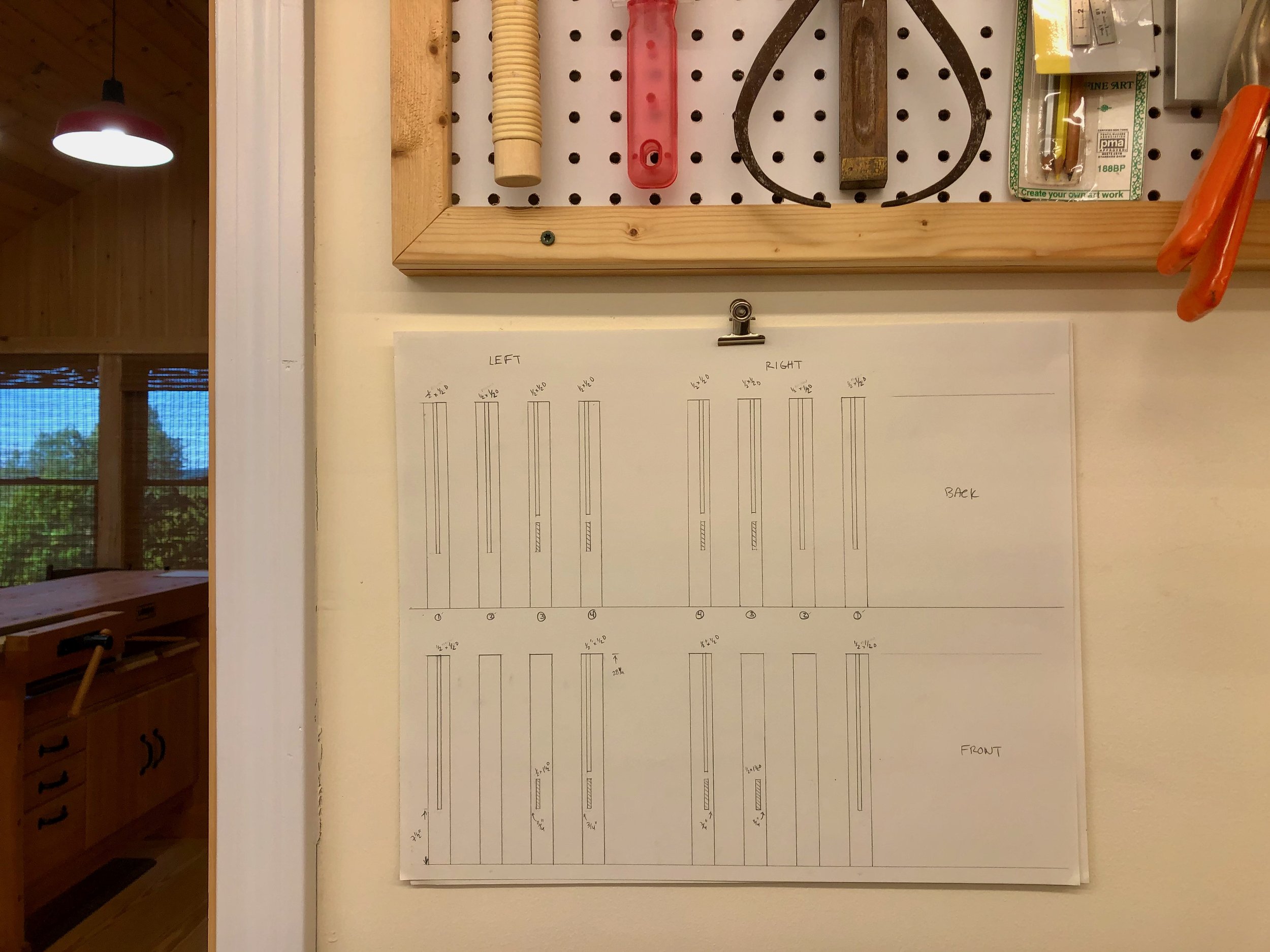
Mortice pattern hung in the workshop for quick reference
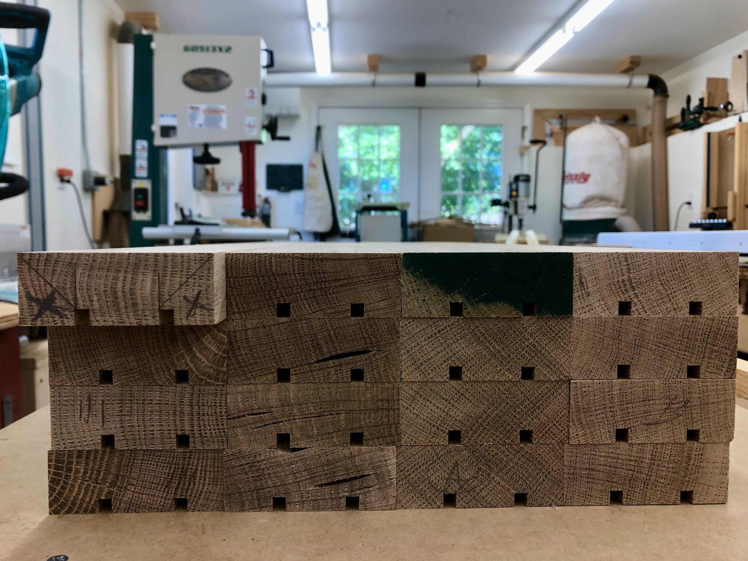
The various cuts were then marked-out in pencil on the leg pieces and the cutting was done at the mortiser and router table. Straightforward stuff, mostly. The one challenge was to mortice the 1 1/2 inch deep sockets for the front and back rails. That’s a lot of oak (read: work) for my machine so I removed some of the volume beforehand at the drill press and it made things go a lot easier. As a final step, the cavities were cleaned-up with a chisel. Their exact dimensions would be used in the next step to fashion tenons on the rails, stiles and corbels. So far, so good.

No. 220 legs

No. 220

Numbers are noteworthy. Most numbers are used to accurately record information but certain ones also define icons. I’m not referring to calendar dates or dimensional specs; rather, those numerical identifiers issued to the bearer with no other significance implied. You know the ones: 5 (perfume); 7 (spirits); 42 (baseball); 43 (NASCAR); 66 (highways); 747 (transportation); more.* They say it all, no matter the language.
* Coco Chanel’s first perfume; Jack Daniel’s original whiskey; Jackie Robinson’s uniform number; Richard Petty’s car; the first all weather route connecting Chicago and Los Angeles; Boeing’s first Jumbo Jet.
Furniture has a few numbers, too, the most famous of which might be 220. Heard of it? It comes from the days of furniture catalogs, and in particular, the catalog of Leopold and John George Stickley. L. & J.G., to use their business handles, were the two youngest brothers of Gustav Stickley, creator of the Craftsman furniture style, and who themselves operated a rather successful early 20th century furniture business. Much to their older brother’s annoyance, their catalog was packed with imitations and derivatives of his designs. But unlike Gustav, these guys stuck with furniture alone and their business, today known as Stickley Audi & Co., continues to outlast that of their benefactor’s which folded way back in 1915. L. & J.G. also made good furniture and around 1912 they designed some “mission” furniture pieces that would come to define the style. Most notable among these was the so-called “Prairie Settle”, No. 220 in their line of goods. Now, thousands of different furniture pieces were produced during this heyday of American manufacture, all numbered, and to be considered iconic among the masses an item needs to truly stand-out as a paragon. The identifying number, through continued reference, becomes synonymous with the nonpareil of that genre. (Don’t you love it when French words come through?) Indeed, L. & J.G. Stickley’s Prairie Settle has become known simply as “No. 220” to both furniture collectors and makers as a means to lift it above the many dozens of other settle variants, all possessing less enduring designs and forgettable catalog numbers.
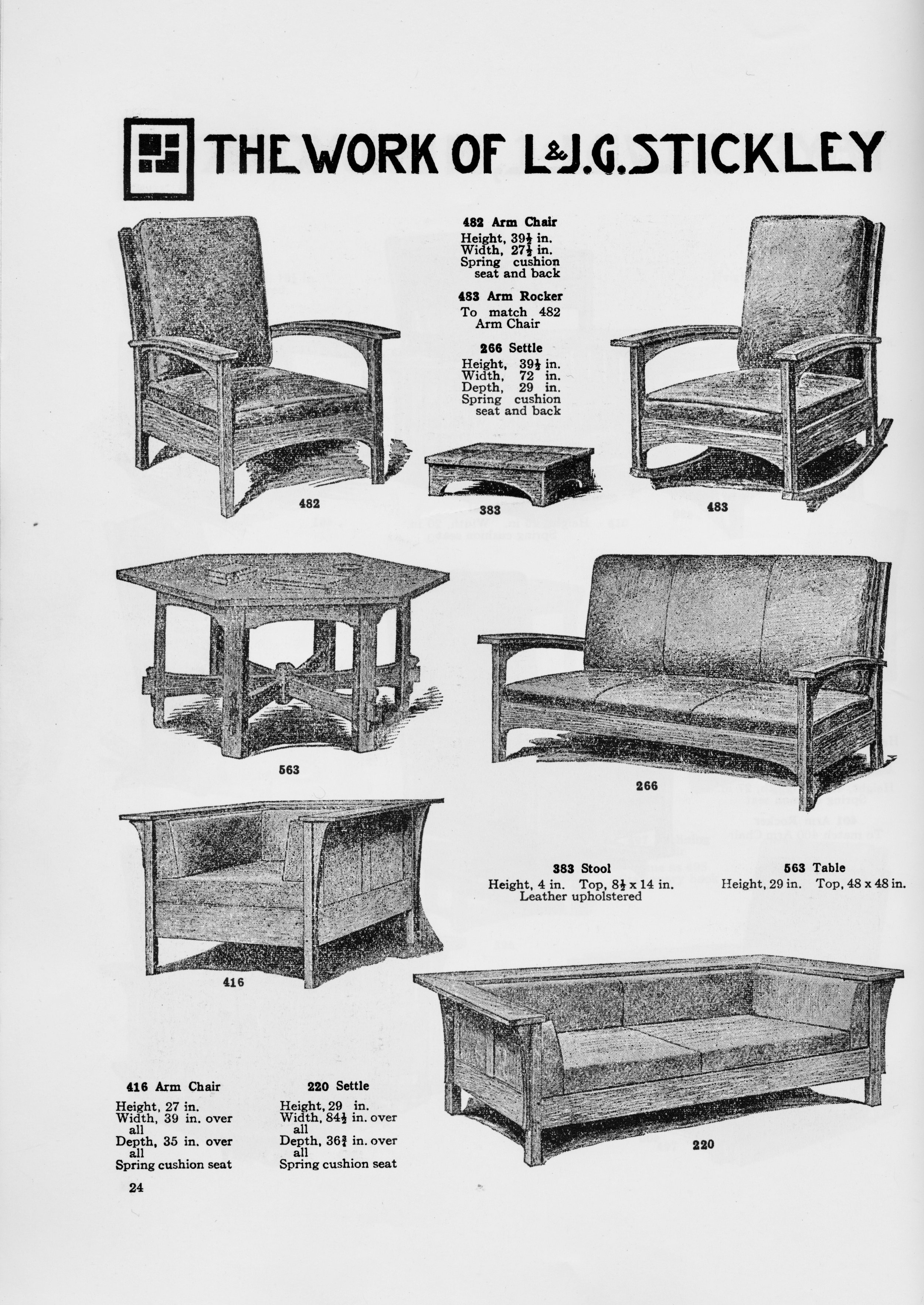
220 Settle, as displayed in the catalog: The Work of L & J.G. Stickley, Fayetteville, NY (c. 1914), p. 24.
reproduced from: Stickley Craftsman Furniture Catalogs: Unabridged Reprints of Two Mission Furniture Catalogs, Dover, New York (1979).
Sketched in pencil and buried mid-catalog at the bottom of page 24 you might wonder ‘what’s so special about this one?’. Well, this settle, and the related arm chair No. 416, contain design elements never before seen in the extensive repertoire of Mission/Arts & Crafts/Craftsman furnishings. The low horizontal lines of the substantial wrap-around arms and rectangular rails make a strong statement and are, in fact, unique. No doubt influenced by architect Frank Lloyd Wright’s Prairie School, which at that time was gaining popularity in the Midwest, these guys from New York (more accurately their designer, Peter Hansen) somehow got it right in a way that has endured beyond all others.
And by “endure”, I mean that it is one of the very few furniture items from the early 20th century that is still being produced according to the original plan. Not only can a new No. 220 be purchased from Stickley today, but a brief Google search reveals that versions of No. 220 are also available on several other furniture websites and from the artisans who market on Etsy. There are also loads of posts in the woodworking forums and blogs describing the exploits of amateur furniture makers still being drawn to No. 220’s bright porch light. You can include me in that last group, too. As my next Project, I am setting out to make the No. 220 settle for our living room. I hope you will enjoy following its progress.
Prairie Settle, No. 220
Photo by H. Peter Curran, from: Stickley Craftsman Furniture Catalogs: Unabridged Reprints of Two Mission Furniture Catalogs, Dover, New York (1979), p. vii.

Cool Costumer
Still intrigued by 100 year-old plans found in the book: Easy Mission-Style Woodworking Projects, I decided to reproduce a useful item for our bedroom while waiting for the next’s Project’s lumber to equilibrate in the shop. Here’s the story.
I have long sought a place other than the floor to stage my “in-use” clothing at night. You know, garments that are too clean to wash, but too “used” to put back into the dresser and so you plan to wear them another day. Then I read about the project on p. 45 of this former manual for middle school shop teachers titled “The Costumer” and was excited to think that a few days of effort in the Workshop and my search might be over. I reproduce that text here:
“The Costumer shown in Fig. 37 is a very good beginning problem for an eighth-grade boy. It is a large piece of furniture to the boy, and one that he will take great interest in. It is a very useful article when finished, for there is no home in which it cannot find a place, either in the reception hall or bedroom.”
Bingo!, right? Now, at first I was put off by the taunts: Beginning problem? Eighth-grade boy?, but then I remembered that the author was referring to boys from the Greatest Generation who would one day persevere in World War II to save civilization and I made my peace. Now all I needed to do was make Fig. 37 in the Workshop.

Fig. 37
from: Worst, Edward F. Easy Mission-Style Woodworking Projects, Dover, Mineola, NY, 2005, p. 45.
Design
I generally do not follow published plans in my work, but vowed to stick close with this one and, in doing so, consciously try to put myself into the world of a 1920s middle-schooler. That world was simpler, yet harder than today’s, especially outside of the big cities. At my father’s farm house in rural Michigan, life in the 1920’s meant no electricity, no indoor plumbing, no automobile (or tractor), cooking with wood or coal on a big steel stove and few conveniences. His “middle school” was the second room of a two-roomed schoolhouse that lacked, among other things, wood shop facilities. I should ask if the family owned a costumer. It was surely a different time.
Anyway, that plan is reproduced below. It looks to be a straight-forward build and the accompanying text suggests alternatives for the joinery depending on your preference for nails, screws or dowels. I’m leaning toward dowels and will probably forego the wooden clothing pegs for store-bought brass as long as the “look” can be maintained. I also intend to use electricity.

Nicely detailed “working drawing”.
Materials
Cherry wood, a new 5/4 flat sawn plank and some left-over 4/4 material from earlier Projects, would be used for the costumer. Brass hardware from FurnitureKnowledge.com would be used for the hooks.

Cherry, cherry, cherry!
Dimensioning
The finished girth of the pole and leg pieces is 2x2 in. and so the first step was to rip the 1 in. deep boards into 2 in. wide strips, flatten one face and then glue them together in pairs. This created two sufficiently thick “leg” pieces and a 64 in. log “pole”. The rough constructs were then run through the jointer and thickness planer to create square, 2x2 parts.
Starting with the legs, I first needed to relieve material from the undersides. This began by using a 1 inch Forstner bit on the drill press, to create “semi-circle” cavities near both ends of each leg.
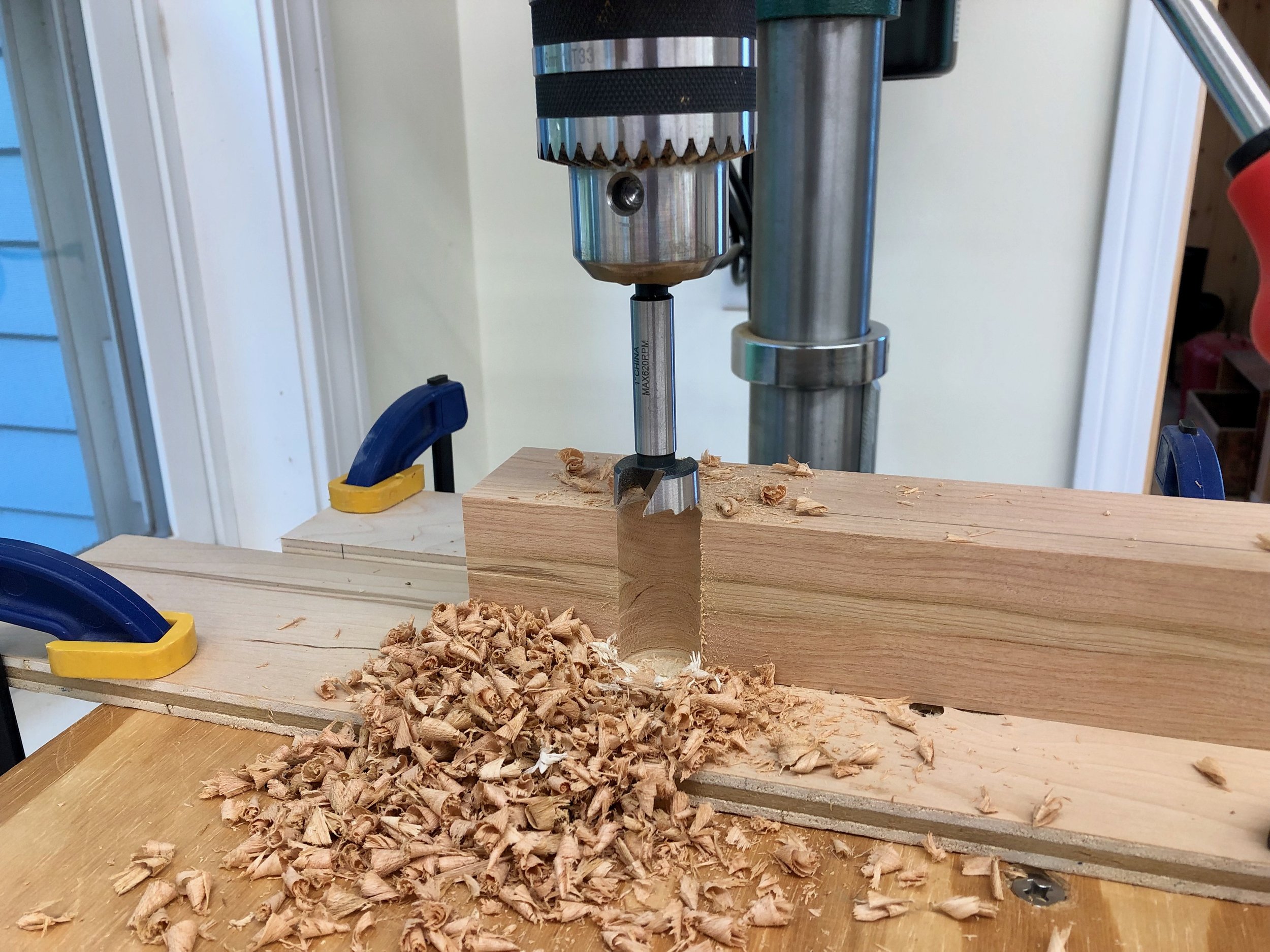
Drilling semi-circles
The material in between the gaps was then removed at the band saw and the resulting surface smoothed with sandpaper. To round the ends of the legs I first drew the desired arc in pencil by tracing the lid of a varnish can. Next the corners were chopped-off at the miter saw and then the extra wood was carefully shaved down to the mark on a disc sander. The picture below shows the penultimate and ultimate forms.
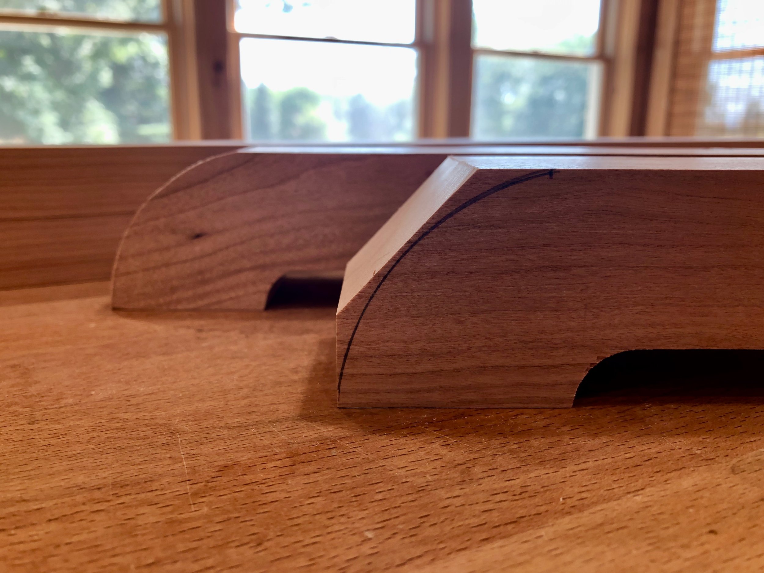
Shaping the leg ends
The legs then needed to be connected to each other in a “cross-lap” joint. This involves cutting wood out of the central portions of both pieces: a 2 inch wide groove from the top of the lower leg; and the same sized groove from underneath the upper one. The depth of each groove equals half of the total thickness and this was found by bisecting the depth of the lower leg, cutting the groove to this depth and then using that result to mark the upper leg before cutting - no measuring. The “cutting” was done with a dado blade on the table saw assisted by my cross cut sled. Nice and clean! Next, a 1 inch square socket was created through the center of both leg pieces. Working one leg at a time, I used the 1/2 inch bit on my mortiser to cleanly cut these out.

Morticed, cross-lapped leg parts
On to the pole. The 2x2 in. pole, fashioned as described above, would need a tenon approximately 1 1/2 in. long to fit within the morticed legs. There are a few approaches to creating tenons and I had been using the dado blade/table saw method on the last few Projects. This generates a lot of sawdust but is a nice way to reproducibly make a series of identical parts. However, I only needed to cut a single tenon in this case, and that 64 in. furniture “part” deserved respect. I did not feel I could accurately and safely work the end of this pole using the table saw. The one tool in my shop that can securely position long parts is the sliding miter saw with a 5 foot table extending off the left side. These tools are normally used to cut (chop) all of the way through a board, but my tool also comes with an adjustable “stop” to hold the blade above the platen should you wish. When used as a sliding saw this feature then allows for cutting accurate grooves and dados into a board. I used this depth stop for the first time to make the four shoulder cuts for this tenon. The four rip cuts to form the so-called tenon “cheeks” were accomplished on the band saw where a ball bearing stand could be used to support the aft portion of the pole during the cut. A slot was then sawed into the center of the tenon for an eventual wedge.
The final dimensioning step was to make the four braces that support the pole. The plan called for 3/4 in. boards here but since another function of the “braces” is to lower the center of gravity, and since I would be using heavy brass hooks instead of wooden pegs up top, I decided to impart more mass by using 1 in. thick stock instead. The instructions also call for the braces to be “sawed out with the turning saw and finished up with the spoke shave and file.” I will instead be using the electrically powered equivalents: a band saw and router. While I am enthused by the nostalgia of hand tool woodworking, I feel I am still trying to get proficient with the power tools in my shop and so favor those techniques … for now. “Choice” is another luxury available today that was not present in the good old days.
For the four braces, I first prepped some 5/4 cherry stock to 1 in. thickness. I then turned to a 3/4 in. plywood scrap and rendered the desired pattern freehand with a pencil. This shape was cut out at the band saw and smoothed to the line using a drum sander to create a plywood “pattern”. The pattern was next used as a template to trace with pencil on the fresh cherry boards, taking advantage of the existing flat and square edges. These lines were “followed” on the band saw (1/4 in. blade), doing my best to stay 1/16 in. or so to the outside of the marks. To create the true curved edges I then added plywood “lips” to the bottom and back side of the pattern so that it could be temporarily screwed into the rough cherry brace along the flat edges. With the pattern on top I could then run these constructs along a flush trimming bit on the router table to create identically shaped and smooth braces (see photos below).
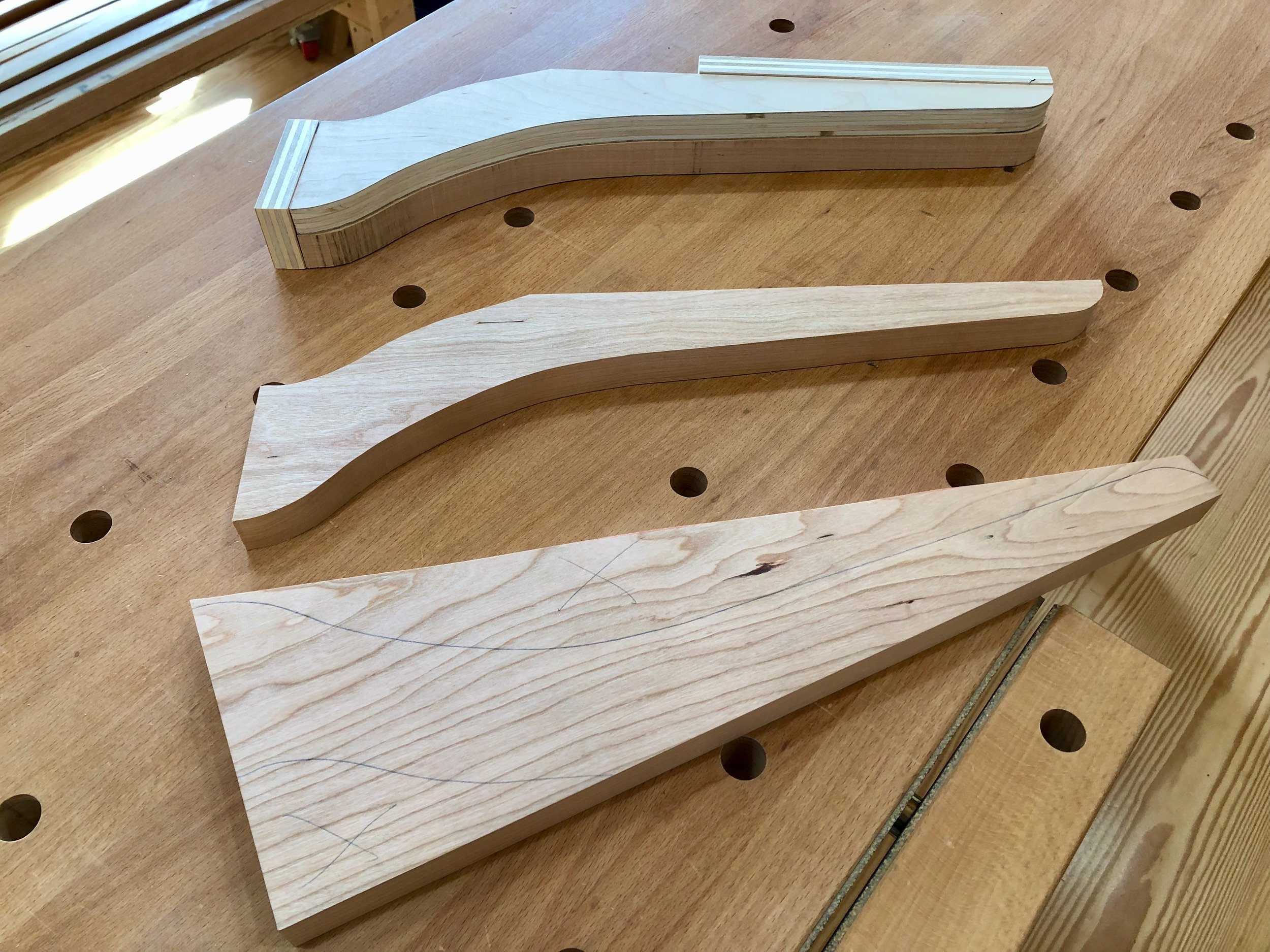
3 of the 4 braces shown in various stages of formation.
bottom: marked board ready for rough cut;
top: rough cut board attached to pattern jig;
center: finished brace
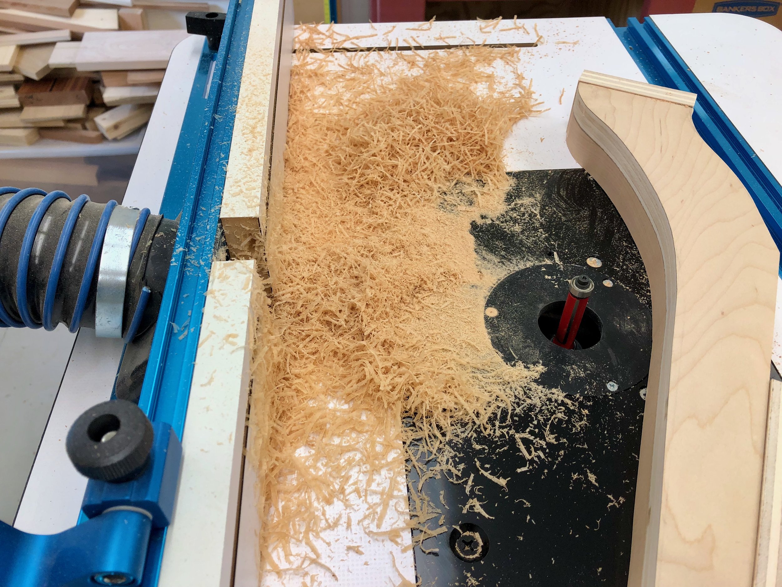
Cherry brace and pattern after having run through the flush trimming bit at the router table.
The braces will be glued to the pole with the help of dowels to keep everything aligned and so 5/16 in. wide holes were drilled into the pole and braces using a Dowl-it jig and hand drill. Dowels of the same diameter were then cut from a maple rod and sharpened slightly with a pencil sharpener.
The very last steps before assembly were to cut the top of the pole to form a peak, scrape and sand the surfaces and then round-off the sharp edges. The miter saw was used to clip the sides 1/2 inch from the top, as per the plan. There are two ways to do this miter cut: 1. tilt the blade to a calculated degree matching the smallest angle of a 1/2 in. by 1 in. right triangle and slice perpendicular to the pole (then rotate and chop again, four times); or 2. pivot the blade on the platen to align the laser line with the cut line and chop (rotate, etc x 4). Choice #2 appeared to be the more foolproof and after four such chops it made for a stately feature on top. All parts were then scraped and sanded to #220 grit. A small round-over bit on the router table was used to uniformly grace the edges.
Assembly & finish
The doweled construction method pretty much dictates the order of assembly on this one. First glue the dowels on to the pole, and then the braces followed by the two leg pieces. Next, a wedge was tapped into the slotted pole tenon to snug everything up. Lastly, before the glue set, screws were used to secure each brace to the legs. Three applications of a gel polyurethane finish was applied followed by attachment of the brass hooks to complete the Costumer, a worthy version of Fig 37.

Mission-style Costumer
Postscript
This was an easy & satisfying Project, and one that utilized every machine in my workshop (bolded for reference in the above story). Of course, it all could have been done as the plan intended without electric tools; instead using handsaws, hand planes, and various other blades and borers. That hand-crafted piece, just as functional, would in many ways be more valuable. The value “add” would come from the extra time and effort applied during construction, but it is unlikely the average furniture buyer would notice any difference between the two versions. That value is only realized by a knowing woodworker or furniture connoisseur who can appreciate the skills required to make things by hand.* And there’s the trap. Does a furniture maker use his/her skills to seek the admiration of peers, even at a price point that makes the product unavailable to most?, or should the aim be to maintain quality and still satisfy the many? In the early 20th century, Gustav Stickley, whose antique furniture now commands high prices, sought the latter. His factories mass produced high quality, mission-style furnishings of inspired design, “… intended primarily to fill, in the most direct and natural way, the actual needs of American home life.”** A costumer of similar design to Fig. 37 sold for $7.00 in Gustav Stickley’s 1912 catalog. Today, the Stickley Furniture Company, a descendant of his brothers’ L.& J.G. Stickley Furniture Co., sells a reissue of their 1909 version for $949.00. (sigh)
* As a collector, I would love to own a costumer made by 8th grade hands from the past century. All of its marks, nicks and unevenness would make mine look flawed by comparison.
**Craftsman Furniture Catalog, Gustav Stickley 1912, p.3.

The Clock/Diaper Bench

Yes, you read that right … clocks & diapers. Projects have been piling up here at the Workshop and any piece that can pull double duty moves right to the top of the list. Here’s the story.
Two very nice things happened this Spring to alter the trajectory of events: 1. the Rocky Mountain clock was completed; and 2. my wife and I became Grandparents for the first time. Now, these events have only one thing in common and that is they both highlight the need for more furniture in our home. You see, to keep the brass movement away from the dusty workshop during construction that clock was routinely assembled-disassembled-reassembled over the course of a couple months on a card table that sits in our “dining” room - a low surface with many other uses. Surely, a purpose-built clock bench would be useful for the next Project. More importantly, we may soon be watching our new granddaughter a few days a week and that same card table seems to be the only diaper changing station available in our recently downsized existence - again, center stage for what might be considered a behind the scene task. It’s not that we don’t have the spare bedroom space, it’s that we lack the proper furniture.
Furniture, those structures all about us that assist our daily existence, are among the most valuable things we will ever purchase without an instruction manual. While most furniture items are constructed to do a specific job, their use, assumed by the maker and implied by the form, is ultimately up to the owner. Thus, furniture leads a precarious existence. Should the need for that job ever disappear, what was once a necessity becomes dispensable and soon begins to resemble junk. Put another way, pieces that get used persist, those that don’t get the boot (vinyl covered living room sets excepted). I was reminded of this hard fact while perusing my latest library book sale find in search of clock/diaper bench inspirations. Easy Mission-Style Woodworking Projects by Edward F. Worst is a fascinating 74 page collection of furniture plans that reads today like a history book. The work is actually a Dover re-publication of chapters 1-3 from a more serious text, Problems in Woodwork, first published in 1921 as a guide for middle school “manual training” (aka shop) teachers. In it you will find obsolete? plans for not one, but TWO clothesline winders, a pen and ink stand, a shoe polishing stand, two versions of a smoking stand and the object of my interest for this Project, the telephone table. Let me be emphatic in stating there is absolutely nothing wrong with the furniture in these plans other than they had lost their purpose over time.

Inspiration for the Clock/Diaper bench
Let’s face it, the past century has witnessed a catastrophic furniture extinction. It’s a dangerous world out there and even items designed to satisfy multiple functions are not invulnerable, for example the billiard table/davenport. While I have never sat nor played a rack on one, I cannot imagine this early twentieth century item was well suited for either activity, and there’s the rub. Even when conditions are favorable (note that both billiard tables and davenports exist among us), to survive, furniture must ultimately be good at its job. With these cautions in mind, let’s move on to our Project.

Rare sighting of a billiard table/davenport
from: Mission Furniture: How to Make It, Henry Haven Windsor (1909).
Design
Admittedly, there was a pretty low risk of failure for this Project as both of its intended uses, clockmaking and child clean-up, only required a sturdy bench top surface for success. And since most of its existence will be spent unused in either capacity, the primary function of this item is to merely look good. Thus, I was searching for a classic design and, in particular, a design where “looking good” in the background was the main mission. Indeed, clock benches have a recognized form, no doubt having evolved to suit a clockmaker’s vocational needs and comfort. But they look kinda “boxy” and, at 42 inches in height, are too tall for diaper changing work. Store-bought diaper changing tables, of which we were a proud owner some 30 years ago, also have a recognizable form. Ours was a three drawer chest fashioned from spray painted particle board onto which was snapped a vinyl covered pad. The problem is that neither of these fully functional items look particularly attractive when not in use. And that’s what clicked for me when I came upon the plans for a telephone table. Back in the day, the job of this furniture item was to sit near the wall where the telephone plug was mounted, support the phone and provide a table and seat for the telephone user. We had a telephone table in our home while I was growing up. I recall we never talked on the phone unless seated at this table, and we rarely sat at that table unless we were on the phone. Our telephone, on a party line with a neighbor down the road, was rarely used and so, although vital for its mission, that telephone table sat in a corner of the kitchen and for the bulk of its life simply tried to look good. Its 1940s design was that of a modified chair, but earlier models were more like slender desks and something that could be easily modified to serve a clock/diaper bench function. The exemplar for our Project is that item on the far left of the book cover, above. I reproduce the nicely detailed plan for this table below, although since all of the dimensions were being enlarged it was of little practical use. I just like the nostalgia of the candlestick telephone rendered lightly in its intended position (upper left).
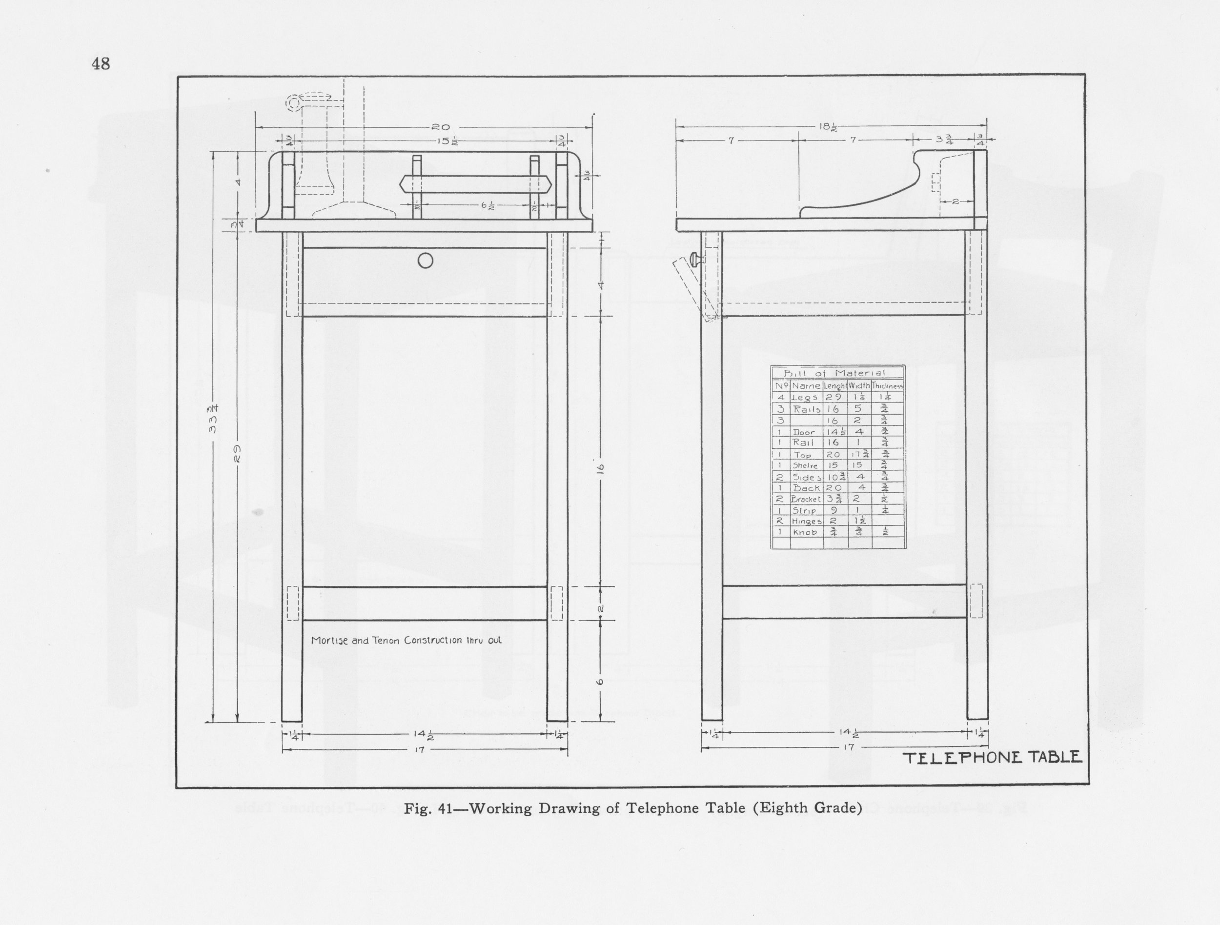
Plans for a telephone table.
from: Worst, Edward F. Easy Mission-Style Woodworking Projects, Dover, Mineola, NY, 2005, p. 48.
The book’s plan includes a hinged door compartment for stowing the telephone book (ask your Mom), whereas ours would include a fully functional inset drawer here - two drawers, actually. My rough plan, below, kept the 42 inch clock bench height but this was reduced a few inches during construction to avoid having to also make a step stool for the diaper changer’s use. I kept the open leg work but added a vertical brace in the center. Looking good so far.
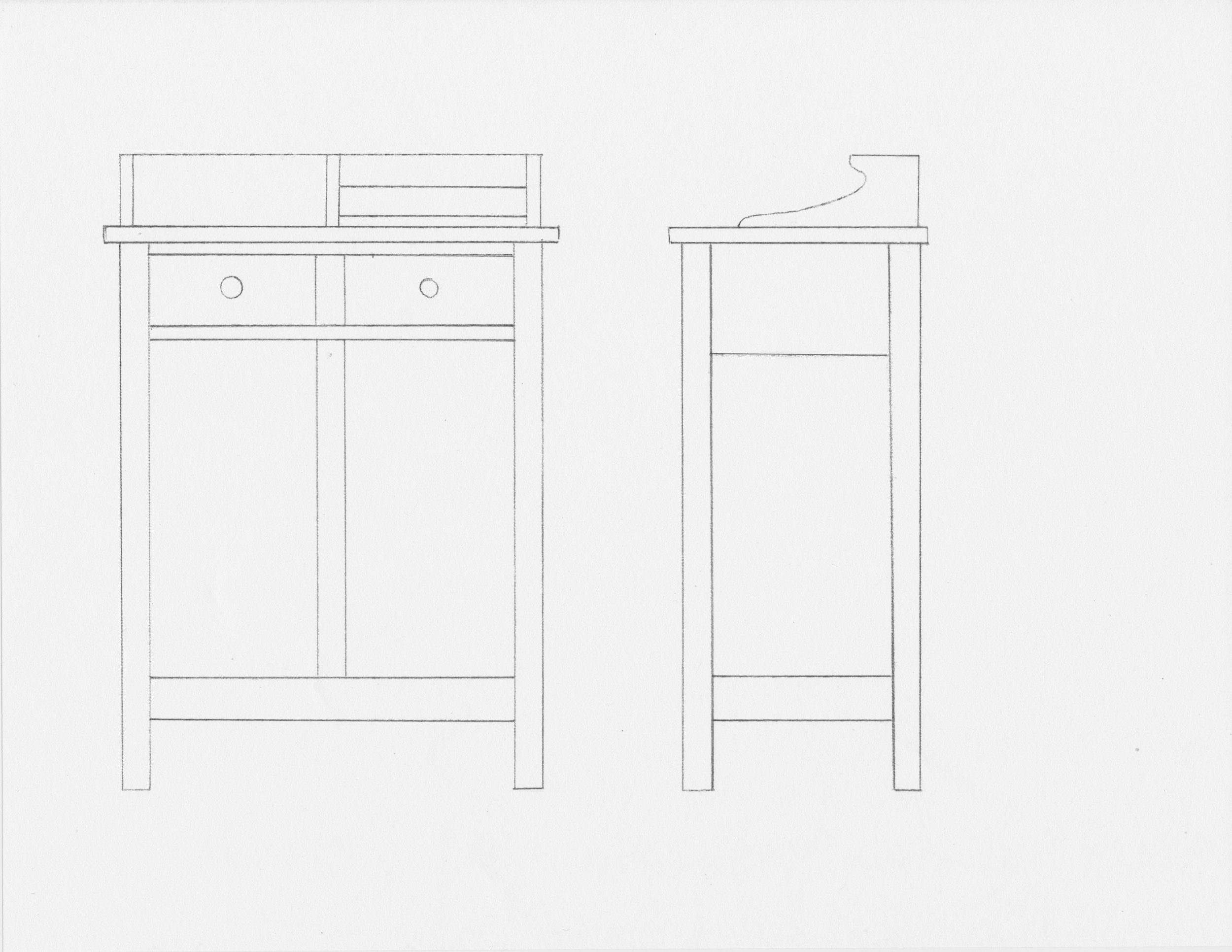
Clock/Diaper bench plan
Materials
In keeping with the tradition of mission furniture the original piece was done in quarter sawn white oak. I also wanted some nice solid hardwood for this piece but was not married to oak. Since time was of the essence and I had recently “workshop equilibrated” some cherry and ash boards for a Korean shelf project, I thought these could be nicely re-purposed here instead. In particular, I had some 4/4 quarter sawn cherry boards that should make for nice and stable leg parts. The table top would come from a 5/4 ash specimen, also with tight and uniform grain. 4/4 Cherry flat sawn boards would be used for the remaining external parts and various oaks and poplar for the draw components. I found some turned Shaker knobs for the drawers to complete the piece in keeping with the original design.

Cherry planks marked for cutting
Dimensioning
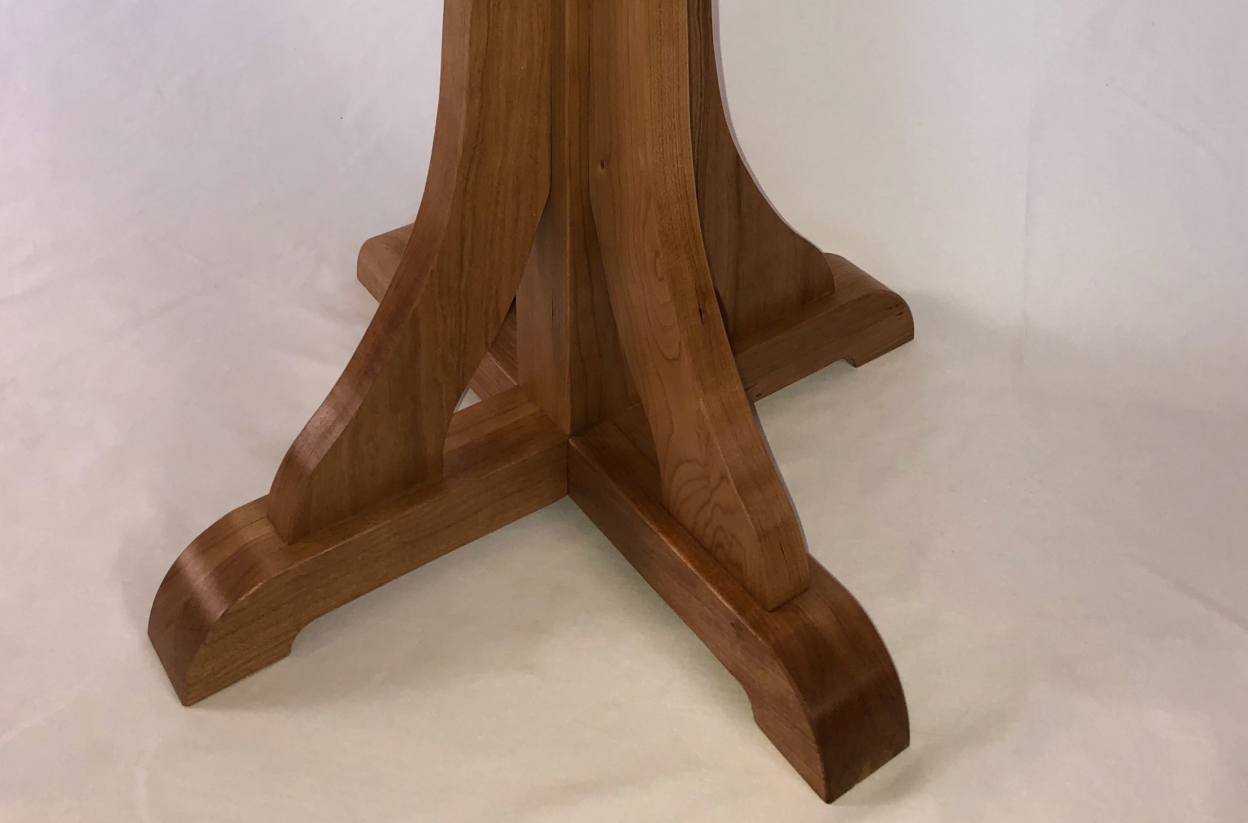
When making tables I like to start with the legs. In the end they will be the least conspicuous element, but during construction that’s where all of the joinery occurs. Our square legs would be 2 x 2 in. but since my boards were only half of this width they would first needed to be thickness planed, ripped and edge joined together. These were then smoothed with the scraper and cut to 35 in. length - as mentioned, a bit shorter than planned but a more convenient height for diaper operations. They would now be heavily morticed to accept the top and bottom rails that would connect it all together. This process can be made simple by adhering to common distances throughout: 1/4 in. set backs; 5/8 in. mortice depth; 1/2 in. wide tenons, etc. A few stop blocks and some forethought as to the order of operations and it all comes together rather easily. The tenoned pieces were fashioned last so that they could be formed to exactly match the width of the morticed openings. This was done at the table saw with a dado blade and then parred further with a shoulder plane to get a nice, “squeaky” fit. To join the center “post” I decided to use dowels instead of tenons. I always wanted to try my Dad’s old Dowl-it (no “e”) doweling kit and found that it worked smooth and accurate for this purpose. A very convenient contraption invented in 1949 and still in production, today.
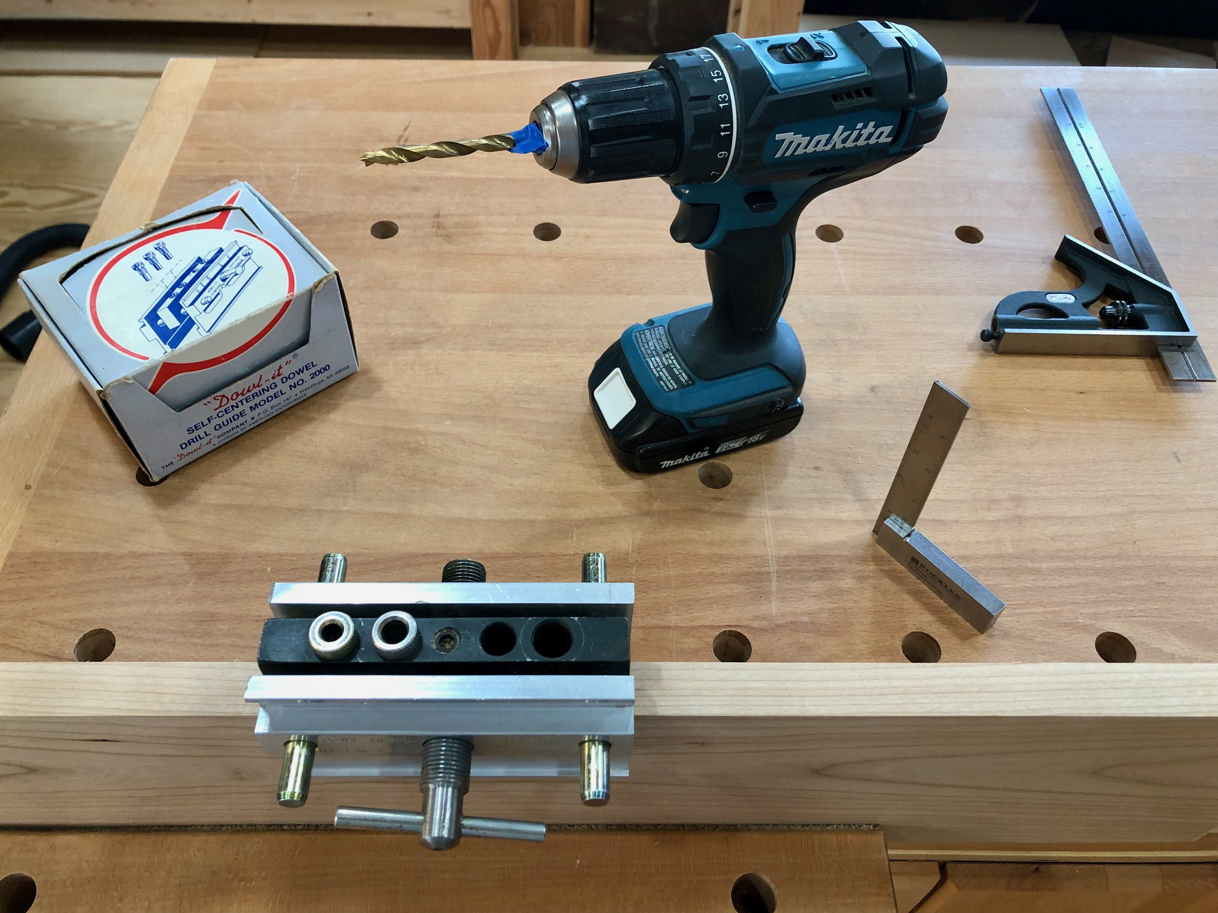
The Dowl-it self-centering drill guide in use
The parts were then smoothed with a card scraper and readied for assembly.
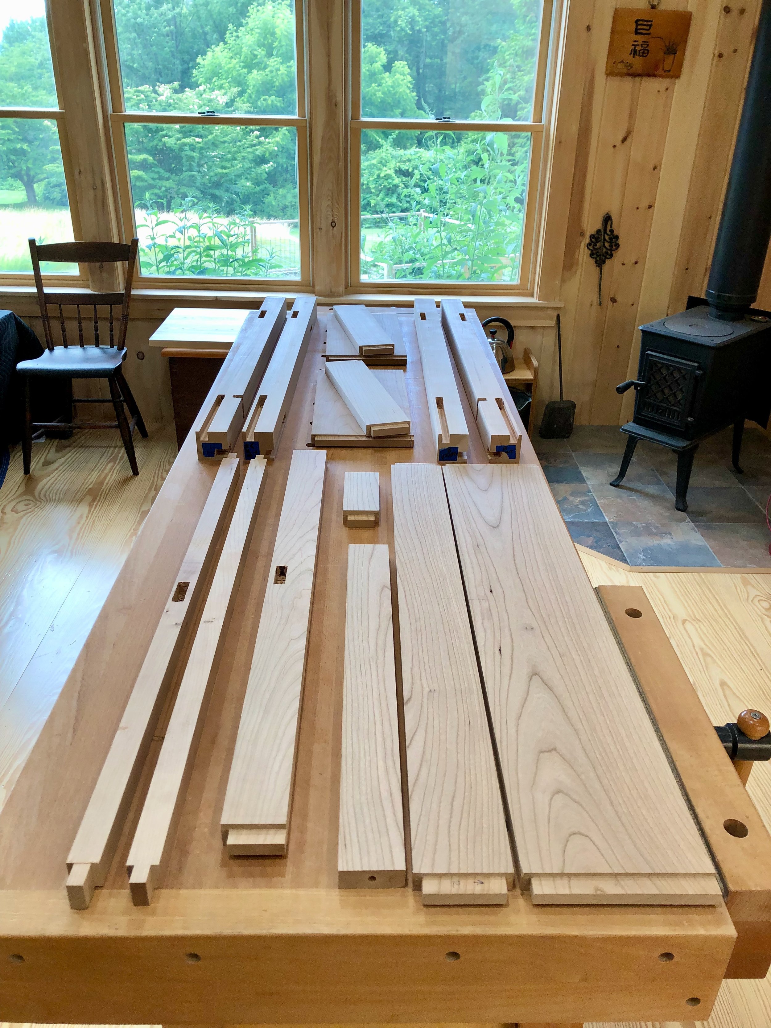
All 15 leg parts ready to go.
I decided to use 3/4 in. plywood as a bottom shelf for the drawers to run on and this would be attached by pocket screws to the frame elements during assembly. The other interior parts assisting drawer operation were made out of scrap oak pieces. For the table top I cross cut a beautifully figured 5/4 ash board in half, thickness planed to a uniform 1 1/8 in. depth and edge joined the two pieces with the aid of wooden biscuits. This was then smoothed and cut to final dimensions with a track saw.
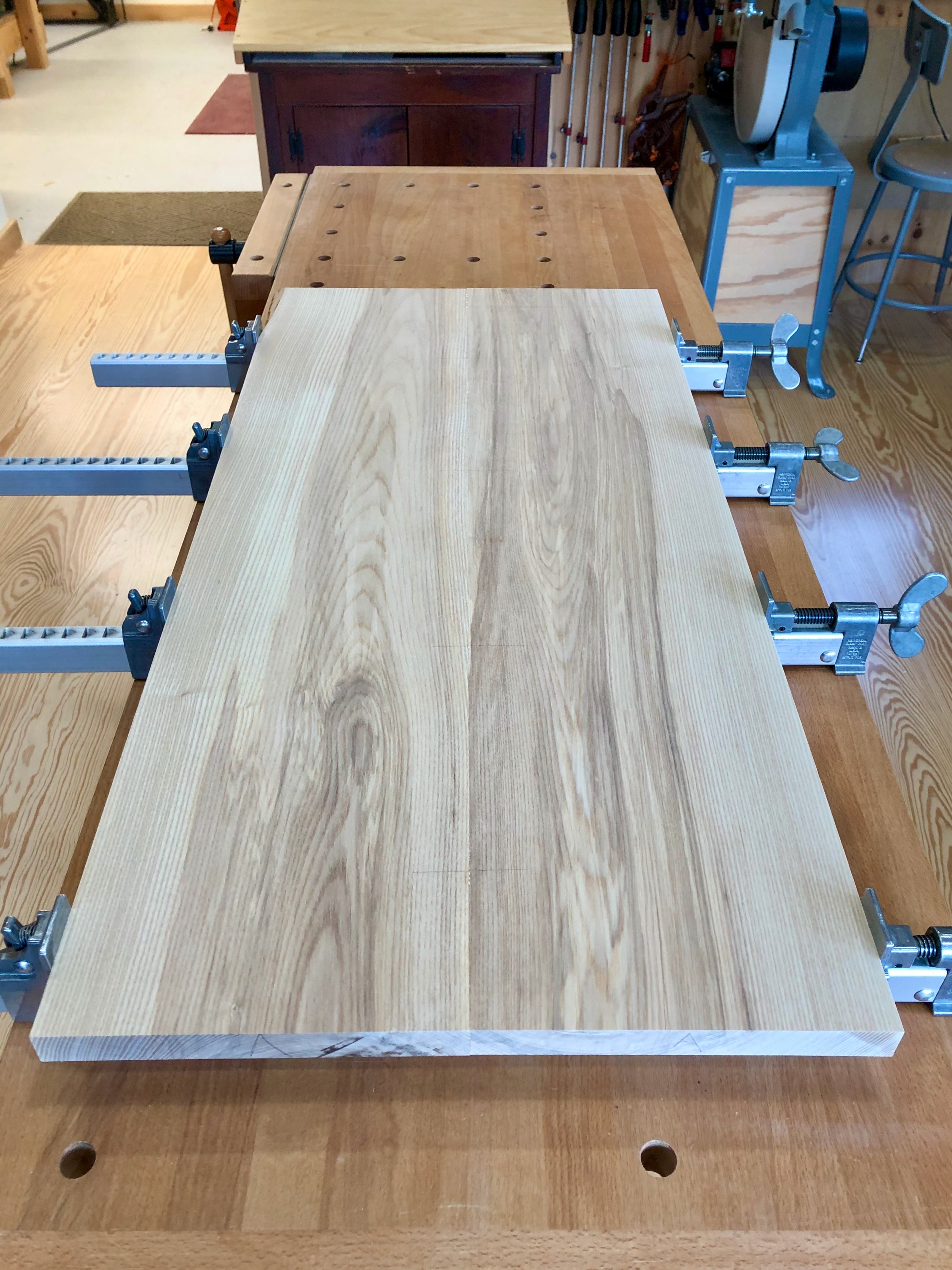
Glueing ash to form the top
Assembly & Finish
I chose to assemble the frame at this point, even though the trim elements for the tabletop would still need to be made. This would let me get started on the drawers, and the bench could also be carried back into the house for emergency diaper use should construction go slow. First, two legs and their connecting stretchers were glued together - one set in the morning and then the second set directly on top of that one in the afternoon. This maneuver lets me be sure that they are identical to one another.
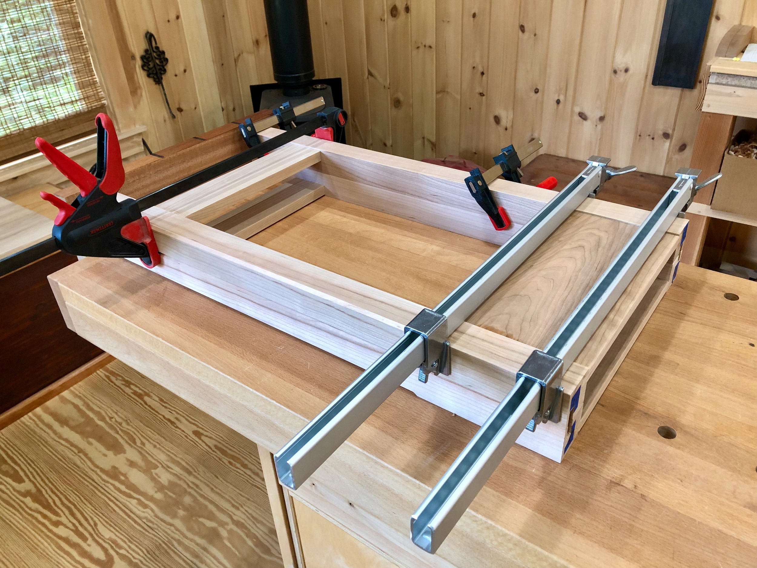
Glueing the second leg assembly, templated on top of the first
Glue-up of the entire frame was accomplished the following day, employing extra assistance from my wife to limit the potential for catastrophe. These pieces can get both heavy and unwieldy towards the end of the tenon pounding & clamping process, but glue doesn’t care. The interior drawer parts were then cut from oak and glued/screwed in place.

Frame intact
Next came the drawers. I bought an extra 4/4 cherry board from a local yard and this would furnish both the drawer fronts and trim along the tabletop. The drawers were put together with the rabbeted half-dovetail joinery used in recent projects. It’s a clean, quick and easy method that yields a handsome product. You recall the sequence: [fit the drawer front; create the box and bottom; futz with the carcass dry fit; glue and dowel the drawer parts together; keep on futzing until you like the way it all looks and operates] x 2. Enjoyable work yet I sometimes wonder if we pay cabinetmakers enough.

Drawers complete
The final element is the trim on top that creates a border for the back and sides of the workspace. This was made from 3/4 in. cherry boards using finger joints to mate the corners. The shop-made finger joint jig used for the Rocky Mountain Clock served nicely here. First the trim’s back board was cut on both ends and then the two sides were taped together and the fingers cut-out in a single session.

Both side trim pieces being cut as one using the finger joint jig.
These side pieces, still taped together were then cut to a pattern on the bandsaw and finally made smooth with a rasp and sandpaper. To me this simple curve, copied from the original plan, evokes both the style and innocence of the 1920’s. Biscuits were inserted along the back to assure a uniform and secure attachment of the trim to the table top, and that top was then secured to the upper legs by way of four figure 8 “table irons”. Finally, a hole was drilled in each drawer front for the knobs.
Dry fit table trim
To prepare the piece for finishing, a light, whole body hand-sanding was conducted. This removed extraneous clamp marks and gave a uniform surface all around. The piece was then sealed and preserved with 3 applications of (satin) gel polyurethane. This coating is very durable and, to me, it is the best way to finish cherry wood without concern for splotching. The knobs, obtained on Amazon.com via China, were of some unidentified hardwood and, while each sports a different grain pattern(?), I decided to leave them alone and not stain them any darker. The existing color contrast of the ash and cherry was enough without adding a competitor. It seemed to work. Following a final (cloth) diaper buff the 1920s telephone table turned clock/diaper bench was complete.

Now, let’s put it to use.


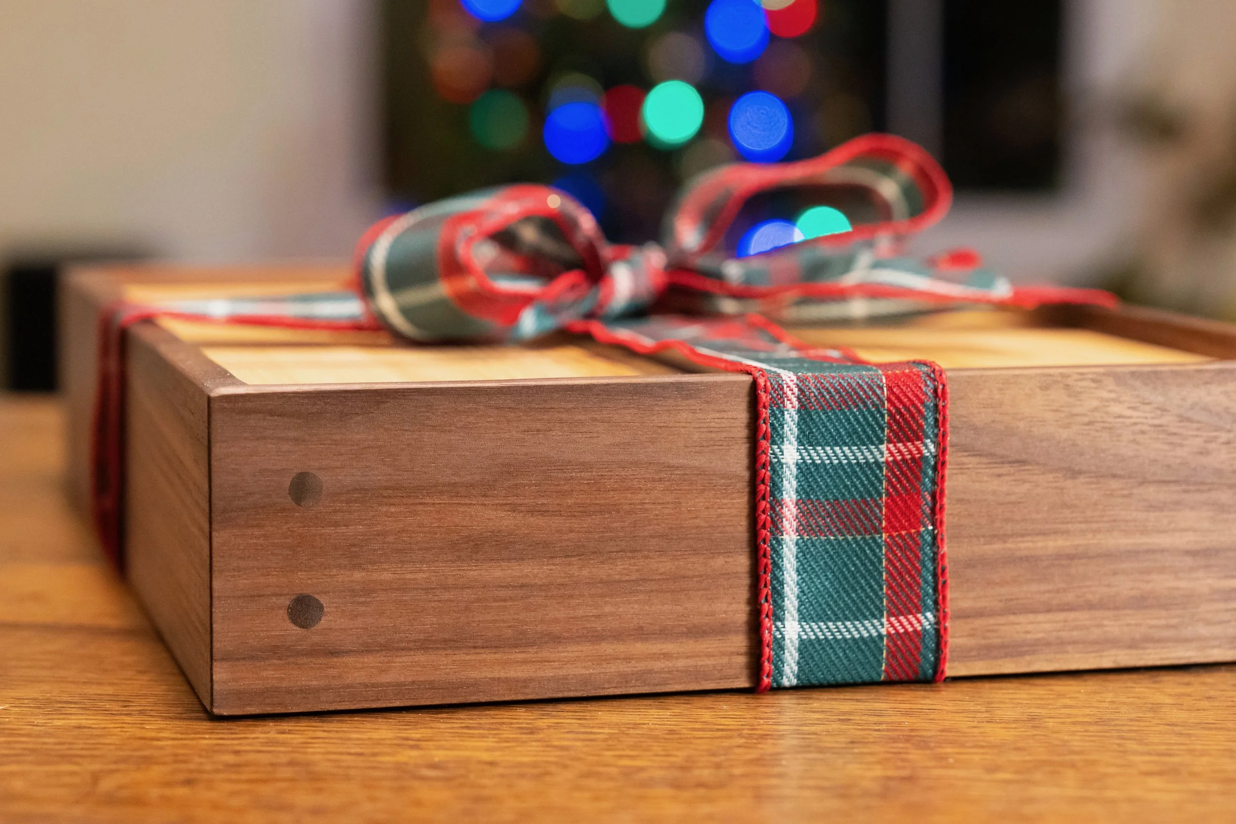
The Candle Box

Some very old and dear friends of ours just purchased a very old home (the oldest, actually) in a very dear little town just outside of Boston. You think we’d be glad, and we were. However, this happy event presented us with a quandary: what to bring as a housewarming gift to a house that’s been “warming” for 275 years? Something solid, sturdy and timeless of course, but avoiding actual furniture yet staying within the bounds of a household accessory, what serves? From the title of this post you already know the solution but please read on.
It is hard for modern Americans to imagine life during Colonial times, when the original portion of this house was built, but it would do us all some good to try. Contemplating history helps to put today’s troubles in perspective and can even evoke pride in our ability to solve problems and overcome hardship. One of my favorite authors, Matt Ridley (biologist, journalist, viscount and former member of the House of Lords), published an interesting book a few years back called The Rational Optimist: How Prosperity Evolves. It is worth a read (and re-read) whenever you feel the need for a dose of perspective. On page 20 Ridley touches on the subject of lighting, specifically how much better we have it today than in times past. Comparing the tallow candles of 1800 to the compact fluorescent bulbs of 2010 and using average working wages for those periods he computes that one hour’s worth of reading light in 2010 costs 1/2 second of labor, whereas this would have required over 6 hours of work in that earlier time. Think about that. And since that comparison was made we’ve moved on to even more efficient LED bulbs. Prosperity evolves! Despite life’s ever present travails we need to appreciate how easy the act of living has become, and smile more often.
Where is this heading? Well we now understand how valuable candles were during Colonial times. In the days before paraffin, candles were generally made from a matter called “tallow” (hard fat) obtained from cattle and sheep, and a lot of effort was expended between pasture and parlor to create the one-and-only appliance that allowed us to see after dark. Once purchased (or made at home) candles needed to be both conserved and preserved. To make them last, they were continually snuffed out and relit, or carried from room to room. And to keep them from being devoured by house mice when not in use they were stored in wooden boxes. Aha!, the candle box.
Design
Candle boxes go back a long way and over time their form had differentiated to serve two distinct functions: 1. long boxes to store brand new tapers; 2. short boxes to store the mostly used but recyclable “stubs”. The simplest examples operate without hinge or hardware, using a sliding top to gain access to the contents inside. That’s the design we will use. Joinery was generally done by dovetails on the corners and the use of either pegs or nails to secure the bottom. This box will be patterned off of a design from a recent library book sale find, Country Pine by Bill Hylton. The dimensions used fall midway between the long and short boxes described therein and were dictated by constraints in the starting material (see below).
Materials
Like the originals, this box will be made out of pine. Specifically, old white pine that I had purchased a few year’s back from a guy named Craig on craigslist. Craig lives in Maine and buys centuries-old, dilapidated buildings there. He then carefully dismantles these structures and resells the wooden parts to people like me. In my “old wood” collection I found a 7 foot long tongue and groove panel and a piece of resawn barn timber that should serve our purpose, nicely. The panel contains nail holed introns spaced 16 inches apart, but good wood could be extracted from the exons in between (scientist talk).

Antique pine lumber.
Dimensioning & Assembly
Once it was decided exactly where along the 7 foot plank the box sides, top and bottom would be extracted from, the rest of the wood prep was straightforward: rip the edges to remove the tongue and groove milling; crosscut the sections to remove the nail holes; joint two edges flat & square; rip to exact widths; thickness plane to 5/8 in. (sides), 1/2 in. (lid), 1/4 in. (bottom); and then crosscut to exact lengths. It’s a sequence that varies little from project to project, yet never gets old. The lid and bottom pieces would be fashioned from two smaller boards each, first edge-glued to create a wider “board” and then cut to the desired dimensions prior to assembly.
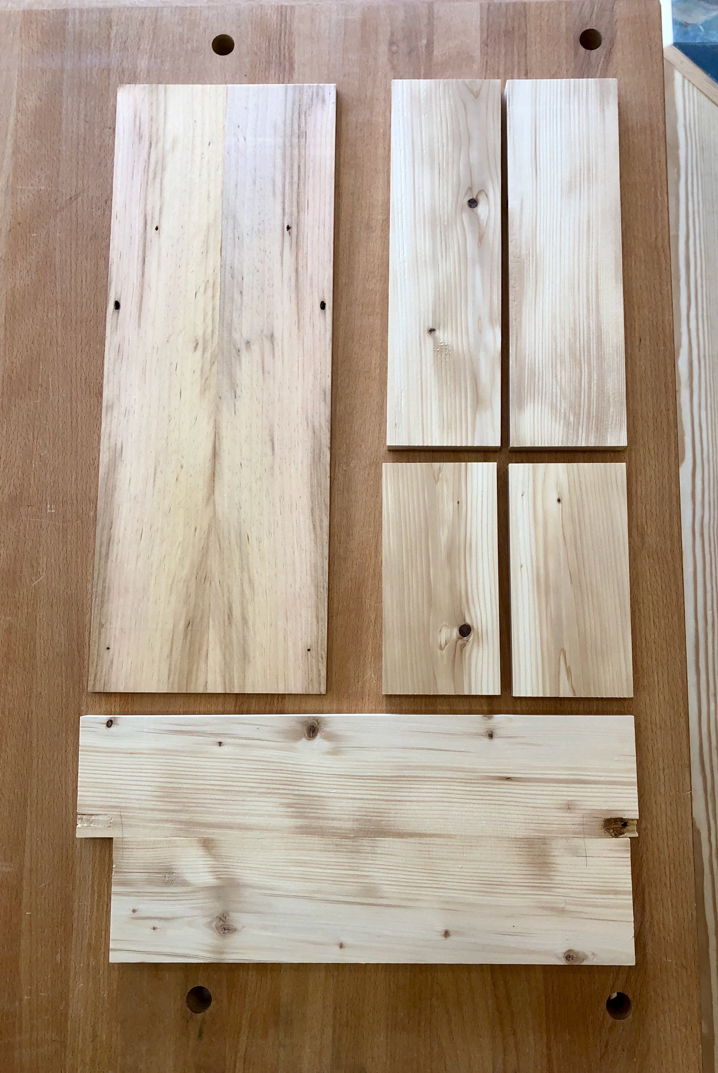
Candle box boards
Next comes the fun part, cutting the through dovetail joints. First, a few final design specs needed to be fixed. The box sides are 3 1/2 in. tall and I decided that two dovetails would be used to join this span. The dovetail joint locks the so-called “pin” and “tail” elements together, and the remaining dimensions in play relate to the width of the pin and the angle of the tail. There are some general norms here associated with the era of construction (like men’s neckties, pin widths oscillate in and out of style) and the type of wood (softwoods such as pine call for a larger tail angle than hardwoods) but since there will be minimal stress on these corners it really all comes down to aesthetics. I chose the maximum width of these pins to be 3/8 in., and tails angled at 10 degrees, or a 1:7 pitch. The two long side boards were then marked on each end for the tail elements, clamped together and sawn as one. This was the first time I tried this joiner’s shortcut and it worked pretty well. I also made the cuts with a Japanese Dozuki pull saw for the first time. On softwoods these saws create nice clean lines with very little effort, I have to say. The other steps all went as planned, more or less, but are not detailed here. Suffice to say I still have a ways to go if I ever want to get good at dovetails.
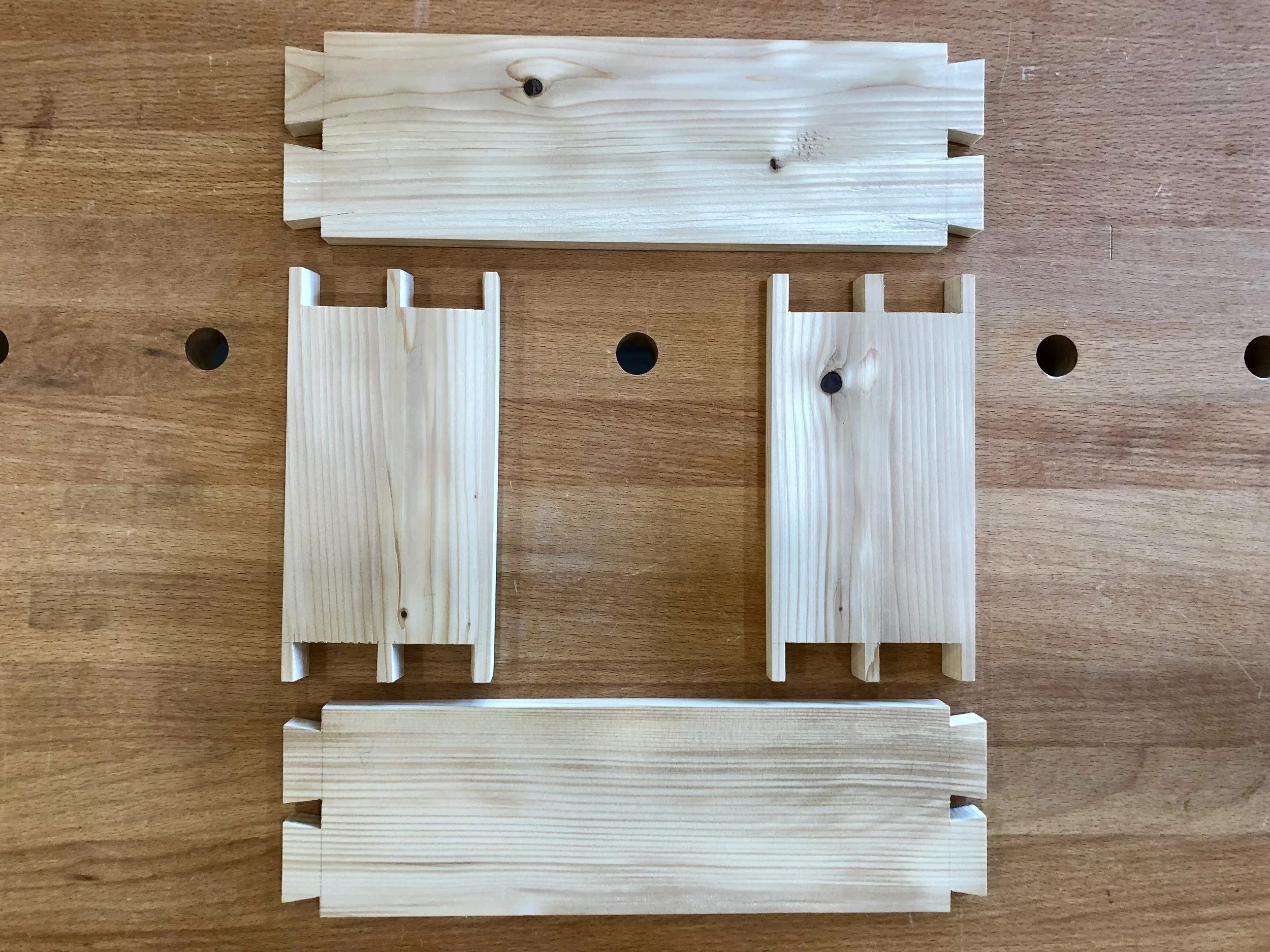
Disassembled dovetailed box
The boards glued-up nice and square, and with a little hand planing, patching and sanding it made a solid box body. Next, the bottom board was cut slightly generous to the box perimeter dimensions and affixed using small finishing nails. The edges were then hand planed smooth and equivalent to the box sides.
The box lid will rest on top of the sides and needs only a groove in which to ride. I chose to “create” that groove by joining “L-shaped” trim boards along the top of three sides of the box. These were made at the router table by rabbeting excess side board stock. They were then mitered at the corners and affixed with glue. Probably not the way it was done in olden days, but the truth is I needed to work around some nail extraction damage in my antique pine and this was a simple fix: cut the wood up and then piece it back together.
After trimming the lid board to the correct width, three sides were beveled to create narrowed edges that would fit within the groove. To achieve the bevel I made a new panel raising jig for my table saw based on one described by Norm Abram (host of PBS’s New Yankee Workshop (1989-2009) and inspirational figure to self-taught furniture makers everywhere) in his book, Mostly Shaker from the New Yankee Workshop. This jig straddles the table saw rip fence and allows one to safely pass the panel to be beveled through an angled table saw blade. Works nice, and using an 80 tooth precision blade it yields a surprisingly clean surface which was then touched-up with sandpaper.
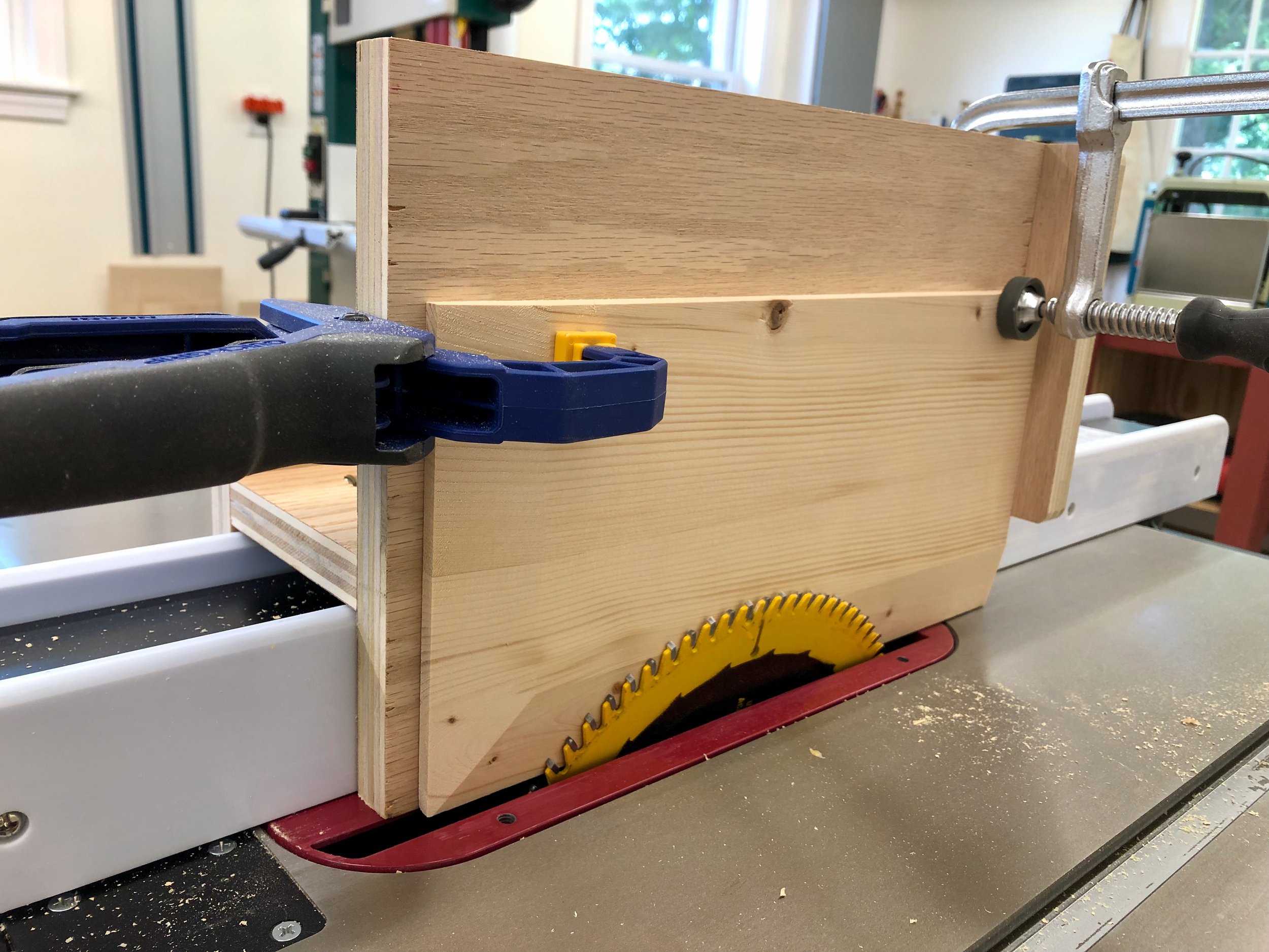
Panel raising jig in action
Once the lid was sanded and running smoothly within its track the final step was to create a finger pull. This meant entering the world of wood carving, or at least sampling the experience. Chiseling a partial cone into the soft pine lid seemed like a simple task but none of my flat edged tools could do the job. I needed a new gouge, of which I found there were plenty of styles, profiles and manufacturers to choose from. I was looking for the baby bear implement here (not to big, not too small, not too curved, etc), and after consulting with a son and nephew, who both do this stuff well, I settled for a tool of #6 curvature in an 8mm width. It worked great for this application and will no doubt be a useful size for other small furniture applications.
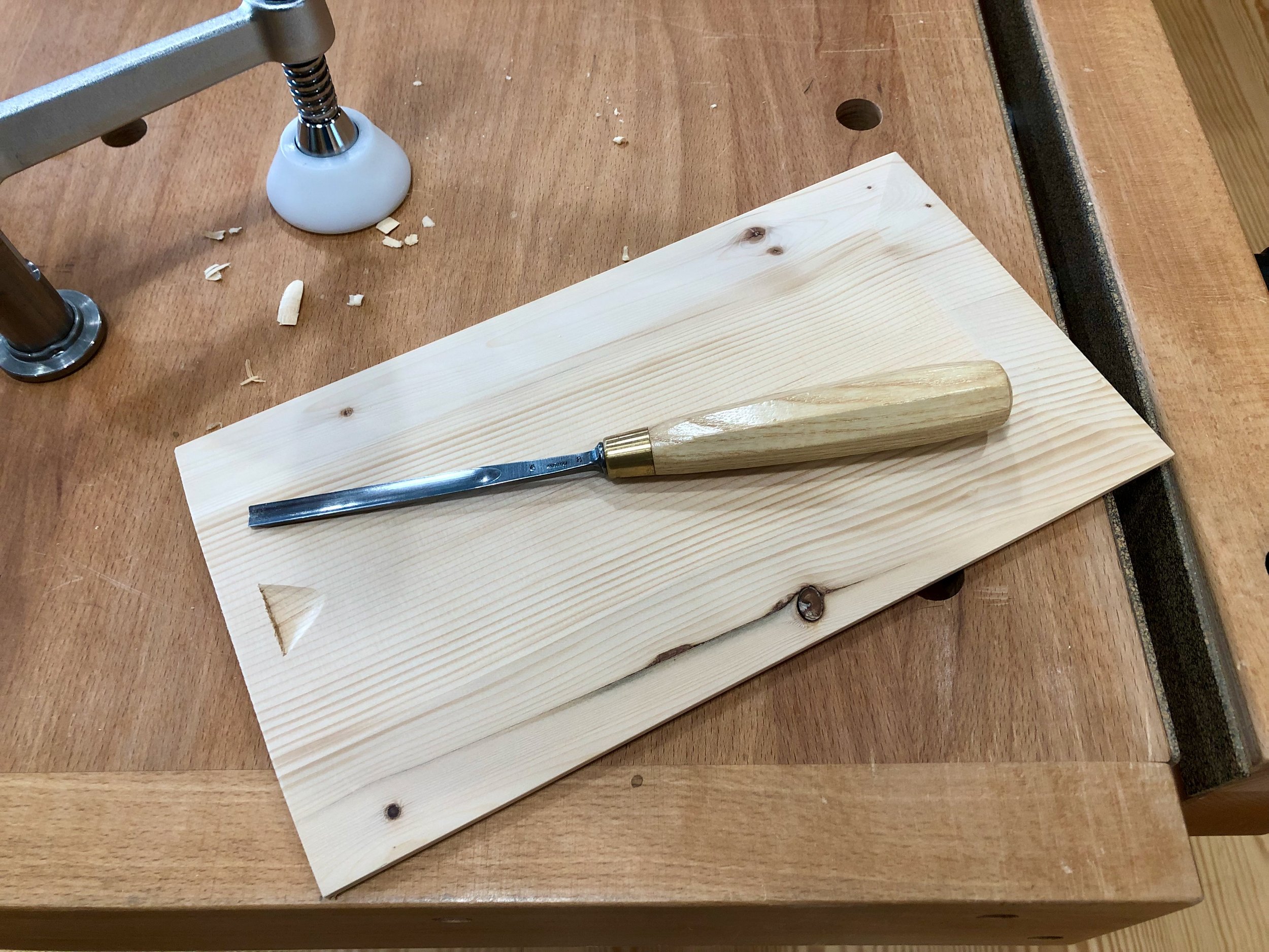
Finger pull and gouge
Finish
The final step was to finish the pine. Original candle boxes almost certainly would have been covered in milk paint, but modern sensibilities favor the look of wood. And the grain on this old pine is so captivating that I decided to go for an “unfinished” look. A single coat of satin gel polyurethane was applied on the exterior surfaces to highlight the changing grain colors, ward off fingerprints and achieve a bit of water-proofing but the internal cavity was left untouched. With a light steel wool buff that old pine felt like velvet and I decided to stop right there. After all these years it still has an eau de terpene air and seems eager to patinate again, in its new home.
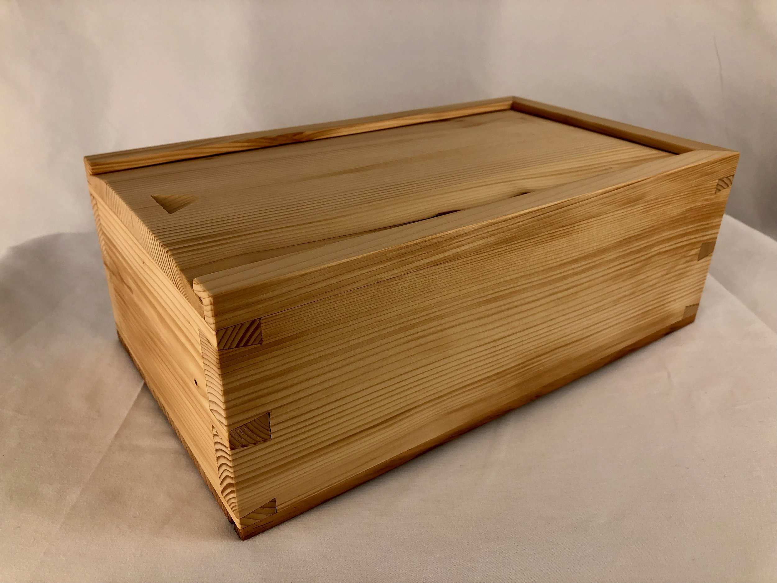
Antique pine candle box …

at home.

Clock of the Westies

Clock of the Westies … get it? (all you Pop Rock fans of a certain age). Its meta-meta to be sure, being a pun on a famous spoonerism of the familiar saying “West of the Rockies”. It also describes my latest Project.
The occasion is the July wedding of my nephew Spencer to his lovely mate, Julia. They happen to reside west of the Continental Divide in Durango, CO which is where this “destination” wedding (for us) will occur, and my wife and I decided to gift them a clock to commemorate the event. Now, clocks are not traditional wedding gifts but they could become so in our family as Uncle Mark enjoys making them and he has no shortage of eligible nieces and nephews. Let’s see how this one goes.
Design
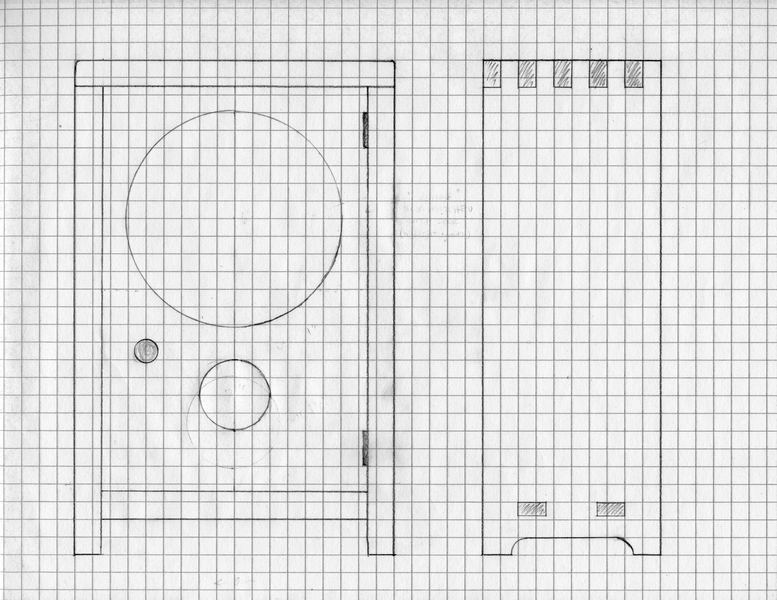
First, a bit about clocks. I like to explore Mission style clocks of the early twentieth century. I admire their “honest” appeal. Eschewing the intricate carving of German pieces, the stone and metalwork found in many French clocks, and the fancy moldings of early American designs, their essence is a simple profile and the seductive texture of wood. They also keep time, of course, but timekeeping was merely table stakes for marketing clocks during their heyday. The popular trends were set, and continually reset, by the case design. (Not unlike marketing automobiles on their chassis appeal.) For this Project I spent some time designing shelf clocks inspired by the Mission styles of the New Haven Clock Co. but decided in the end that these were still too made-up, too fancy. In my mind, a Rocky Mountain clock case needed to be plain-spoken and natural; in a word, “rugged”. But a rugged object that could still appeal to the eye. Going back to Arts & Crafts basics, I then conjured a modern version of the iconic Stickley mantel clock and found it to be both compelling and make-able. My guiding principle was: thou shalt not distract from the wood. A few changes were proposed in this case compared to Stickley’s design. Instead of a dodecagonal face with numerals, this one would be round and numberless (think Movado museum watch). I could also echo the round clock face opening with a circular pendulum reveal, common in other Craftsman and Shaker cases. A rough plan was drawn on graph paper but I was prepared to tweak all dimensions once the clock movement arrived and vital measurements could be made.

Materials
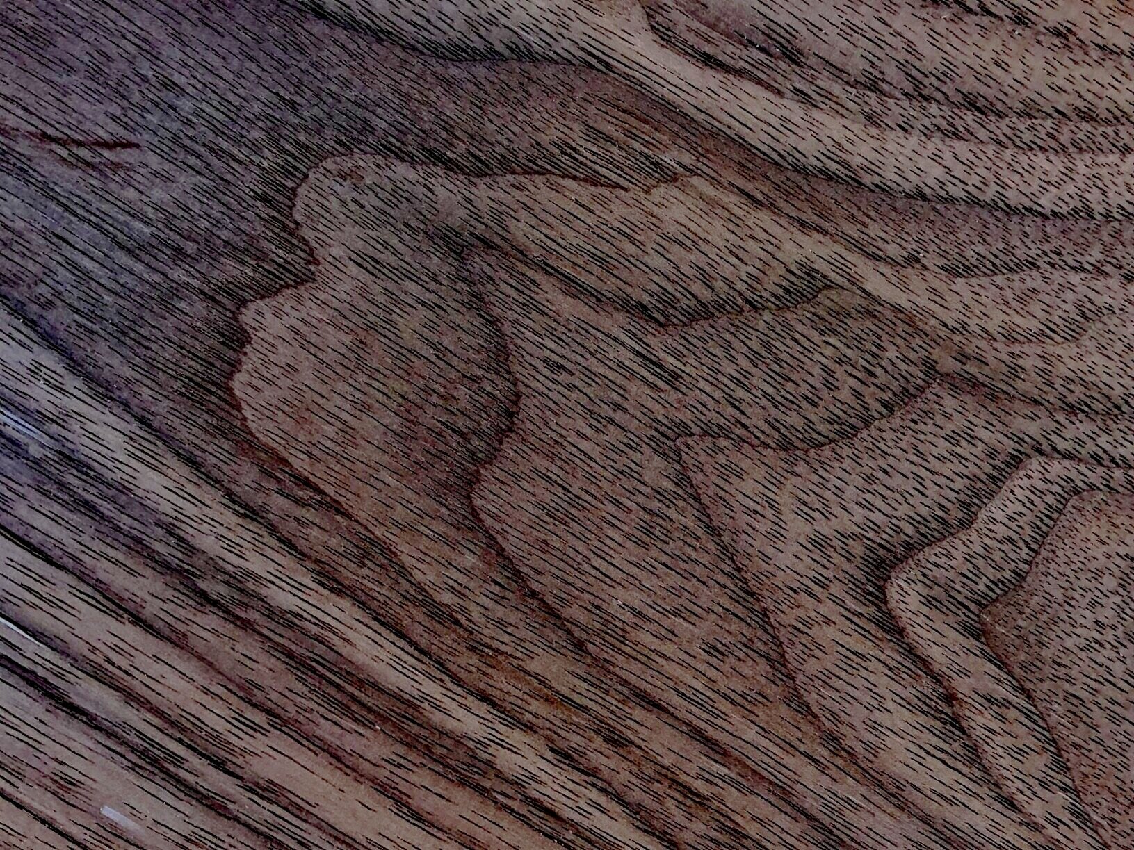
Butternut was the lumber chosen for this piece. This wood, Juglans cinerea, works easily and is remarkably soft considering its close relation to black walnut, Juglans nigra. With its dramatic grain and subtle orange-brown tones, butternut is the wooden equivalent of tanned leather. A single, 5 in. by 8 ft. plank of 4/4 stock should be all it takes to make the case. The clock face would be made of a less figured wood (TBD).

Butternut clock stock
The rest of the materials are all metallic and mostly brass: the clock movement; pendulum; key; gong; grommets; hands and hinges. Everything but the hinges was procured from Clockworks, a terrific online clock parts store. Primarily serving the clock repair trade, they carry all manner of high quality horological goodies. Also, their informative website and live technical support are extremely helpful to the amateur clockmaker.
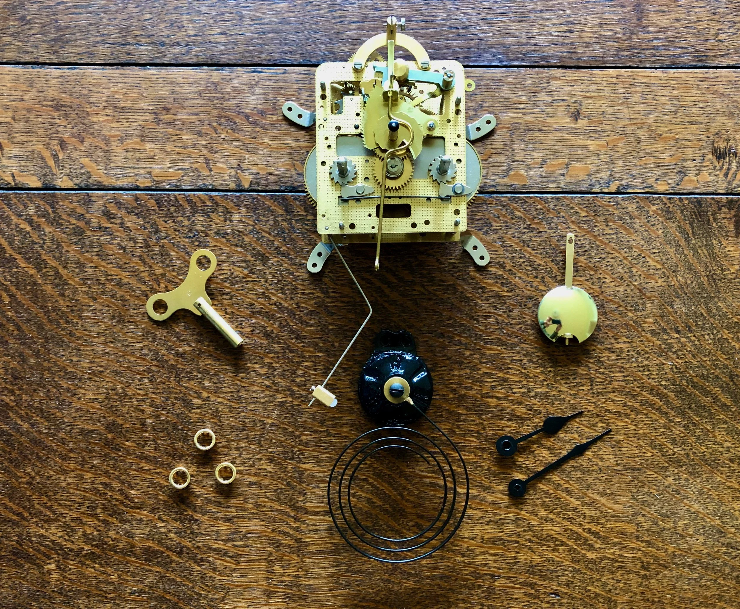
Clock components
Dimensioning
The clock case would be made from 3/4 in. boards, whereas the backboard, door and face would use thinner material. These thicknesses were created using the appropriate power tools and the mill marks then removed by hand before making the joint cuts. Like Stickley, I decided to use through tenons to fasten the bottom of the case, but opted for finger joints, rather than dovetails, for the top corners. Both finger and dovetail joints look beautiful when finished and, admittedly, both are overkill for this stress-free construct. However, finger joints would let me try something new and they also keep the shape repertoire for this elemental design down to two (circles, rectangles, trapezoids). But before I could cut the finger joints I needed a new jig.
Finger joint jigs come in several forms depending on whether you wish to create the joint using a router or table saw and, although commercially available, I prefer the homemade versions. Jigs for the table saw can be created by tinkering with a cross cut sled or by modifying the saw’s miter gauge. I opted for the table saw miter gauge version and, specifically, that jig described in a recent library book sale find, The Accurate Table Saw by Ian Kirby. Basically, this jig provides a mechanism to smoothly pass a vertically-oriented board through a spinning dado blade. The critical element is a 1/2 in. wide block of wood (aka key) that is affixed 1/2 in. to the right of the blade slot. The joint is cut by repeated passes through the 1/2 in. dado blade as the board is “marched” rightward in 1 inch steps. It works great, is easy to make from shop scraps, and you can get the whole concept from the picture below.
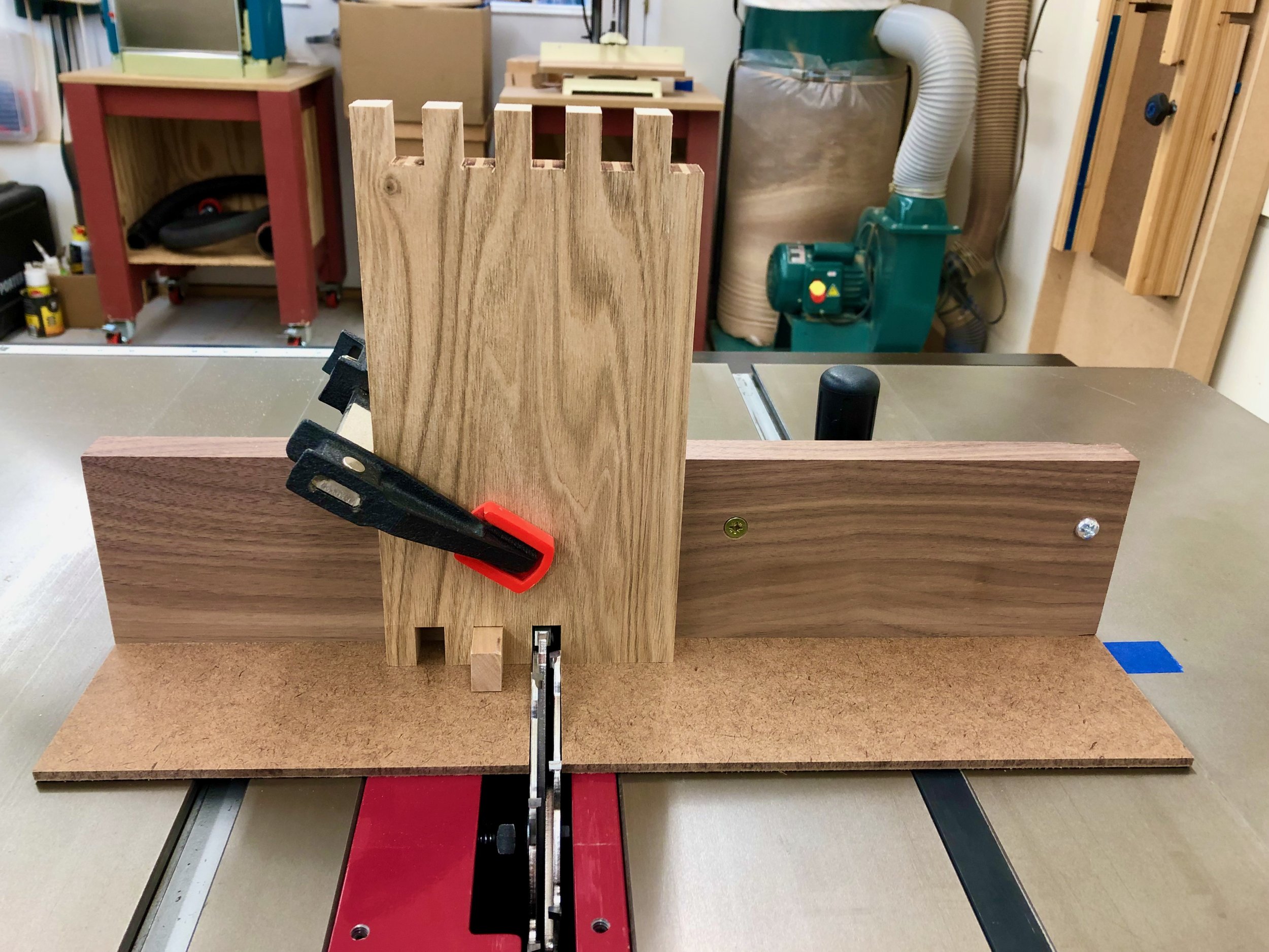
Shop-made finger joint jig in action
The fingers were fashioned on the top and side boards, and I also found that a simple modification of this jig could be used to accurately cut the tenons in the floor board. These were then dry-fit to describe the enclosure. Next, the clock mechanism was assembled on a stand and placed within the “case” so that the floor height and other critical dimensions could be fixed. The mortice sockets for the floor and rabbets to accommodate the backboard were now ready to be fashioned. Figuring out how to attach the movement to the case would await the next dry-fit.
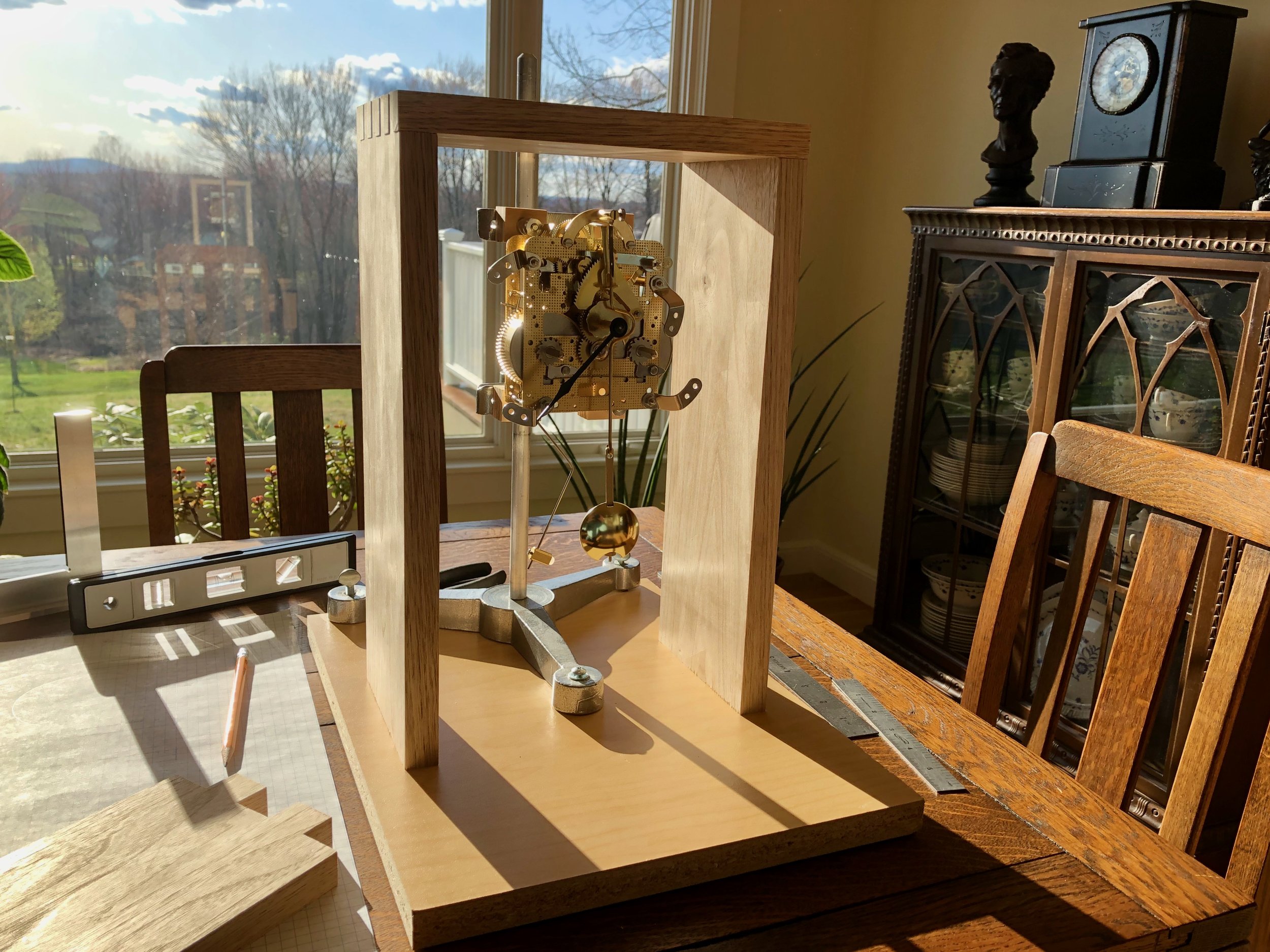
Clock movement mounted on a stand within the partial case assembly
Two mortices were cut (1/2 x 1 in.) on each side piece and then the tenons of the 3/4 in. thick floor piece were rabbeted to the correct 1/2 in. depth for a snug fit. Next the backboard was constructed by re-sawing a 4/4 butternut plank in two, thickness planing these pieces to 3/8 in., edge joining them together and then trimming this “new” board to the final width and length. A rabbet was then created along the back edge of the four case components to house the backboard. The design of this particular clock movement requires that it be mounted to the back of the case. The clock and backboard would then be secured to the case sides by screws to facilitate its removal for servicing of the mechanism over time. However, attaching the clock directly to the backboard would place the clock hands too “deep” within the cavity and so a square piece of 1/2 in. plywood was affixed to the inside to act as both a shim and a stiffener to prevent warp. A small cove cut into the bottom of the plywood allowed the gong to nestle into its proper place. The clock movement was screwed to the center of this board and then the entire construct attached to the dry-fit case using brass, pan-heads.
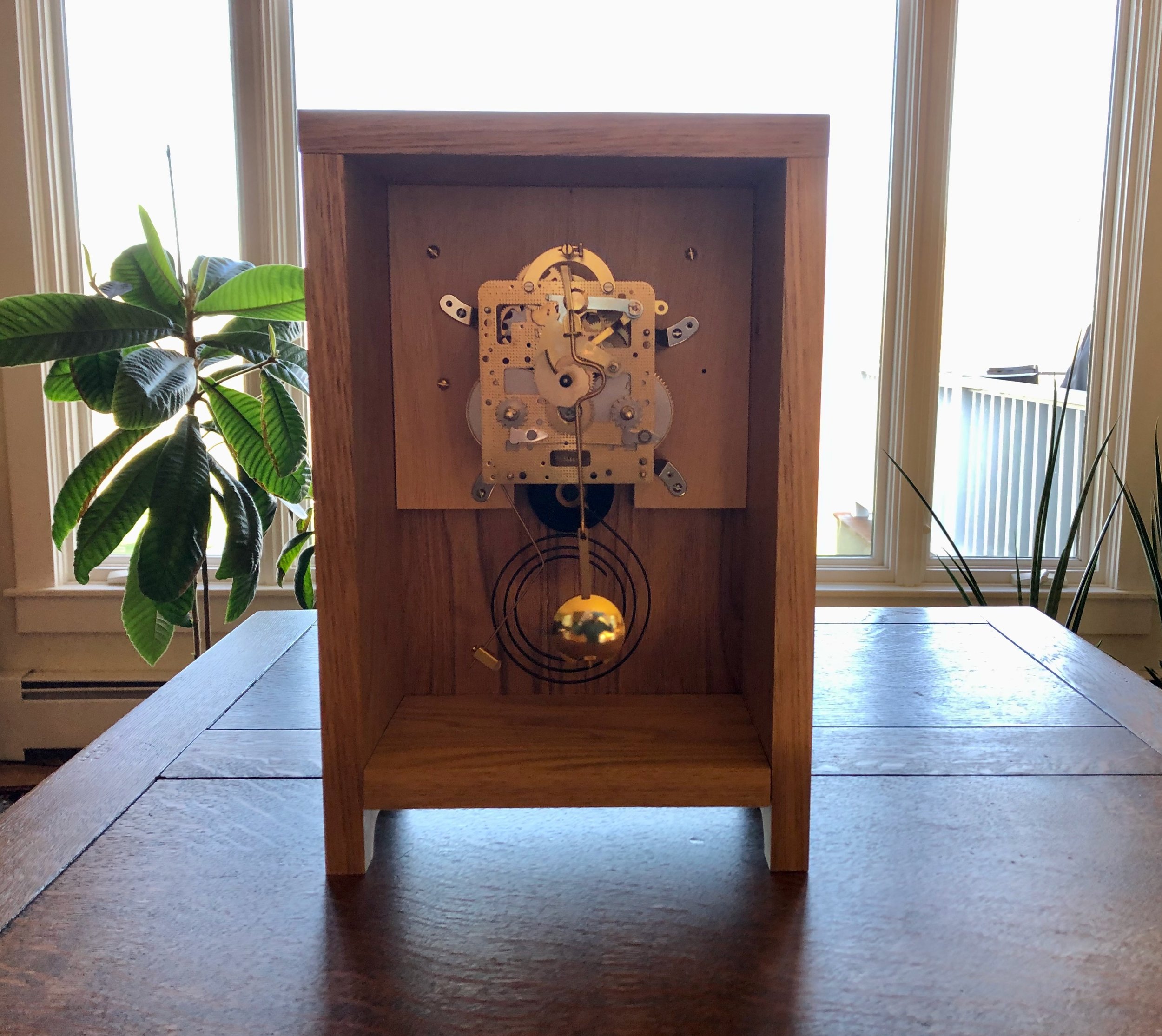
Movement and gong temporarily mounted in place
With the movement mounted in its final position the pendulum was attached and mock doors were cut from cardboard to help visualize how the different circular openings would work. In this design, a circular opening in the door creates the clock “dial” and, due to the chosen case width, this circle must be centered at a point 3 3/4 inches from the top and sides. Located 4 3/4 inches directly below this coordinate would be the center of the pendulum, and a smaller circular cut-out was proposed to serve as a window on its movement. The diameters of these circles were the design variables in play. The hands selected for this clock serve a 6 inch face, and a circular cut-out of this size would be the largest feasible opening in a 7 1/2 inch wide door. I liked the boldness of going to the max here. Below this, the pendulum bob could be nicely framed within a 2 inch opening and so a mock door with a cut-out of this dimension was tried first. Result: too large; too much underlying commotion. Next, to focus solely on the pendulum bob, a 1 inch diameter hole was tried. Result: too small; too distracting. I could have kept experimenting with other diameters but based on the first two results I was now concerned that any opening here would only detract from the beauty of the clock as an object. I then tried a mock door without any pendulum window. I liked how this version celebrated the proportions of dial opening to door mass and then I recalled the “thou shalt not distract …” motto. Decision: forgo the window; let wood do the work!
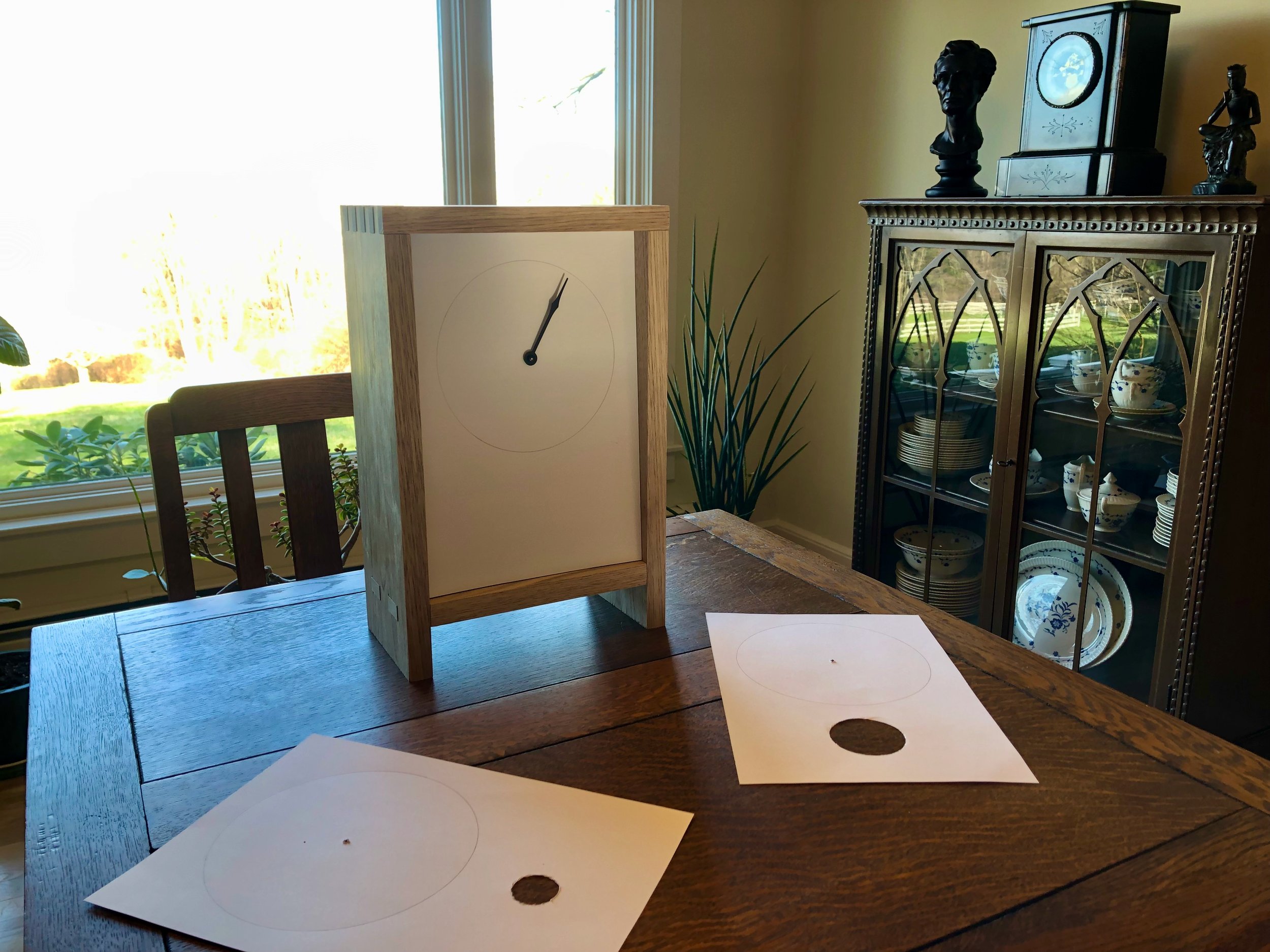
Mock clock doors
To make the door, the remaining butternut was re-swan at the band saw and subsequently thickness planed to a 5/8 in. depth. This was then chopped, jointed, ripped, glued and smoothed (all with great care) to create a slightly oversized door panel ready for the circle cut. A similar sized board was created from the leftover “end cuts” to serve as a test subject for this crucial procedure. To fashion the circle, I decided to use an adjustable circle cutting device at the drill press. This “cutter” consists of a bit that fits into the drill chuck and serves to register the center of the desired hole. Attached to this bit is an adjustable arm that holds a sharp piece of steel which spins along the desired circumference, thereby scribing a circle into the wood as the drill press is lowered. During the test run I found it was difficult to dig more than halfway into the board without the cutter continually seizing up. To remedy, I removed the board from the drill press, completed the central hole puncture with a hand drill, flipped the board over and re-mounted the circle cutter with precise alignment using this hole as the guide. The remainder of the cut on this “backside” proceeded as before and just as the knife began encountering difficulty it broke through. The result was a nice clean circular edge on both surfaces with a fuzzy “rind” of rudely severed fibers left in between. The rough parts were knocked down using sandpaper to create an acceptably circular hole. Cutting and sanding the “real” door in this manner proceeded without incident. Finally the sides of the door were shaved with a hand plane to achieve the desired fit within the frame.
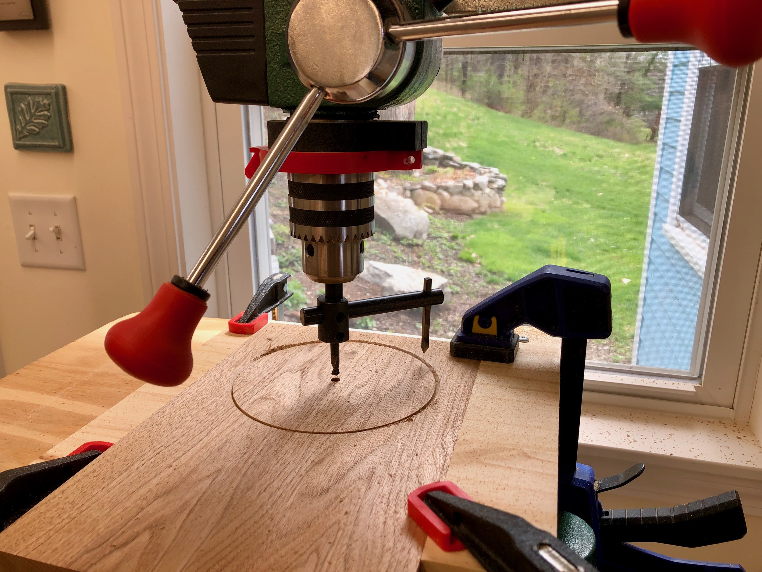
Cutting the “dial” on the drill press
To complete the case I needed only to: 1. shape the legs; 2. mount the clock face board; and 3. create mortices for the door hinges. The legs were easily fashioned from the side boards by drilling two 1 1/4 in. holes along the bottom edge at the drill press and then trimming the resulting “isthmus” at the band saw. For the clock face I wanted wood of a color that would both harmonize with the butternut case and also allow the black hands to be easily read at a distance. I chose some antique curly maple left over from the Stationery Chest Project for this. Its subtle character fits in nicely and could either be left bare & light or dyed some interesting shade, TBD. The chosen board was thickness planed to 5/16 in., smoothed and then cut to size. The tricky part is drilling holes for the hand shaft and winding arbors at the proper positions. Happily, upon request, Clockworks was able to provide the numerical spacings for these elements, as direct measurements on the movement are difficult. Once the holes were drilled I was able to rout a shallow trough on the backside of the face, above the hand shaft, to allow the movement’s front-mounted suspension spring and pendulum leader to swing freely. Four spacers were then prepared from butternut scraps that can be attached to the interior sides during assembly. These will support the clock face at the proper distance from the movement. Finally, mortices for the brass hinges were cut into the door and case side using a chisel. This is always a tricky job for me, but with patience it appears that I managed to cut out just the right amount of wood this time.
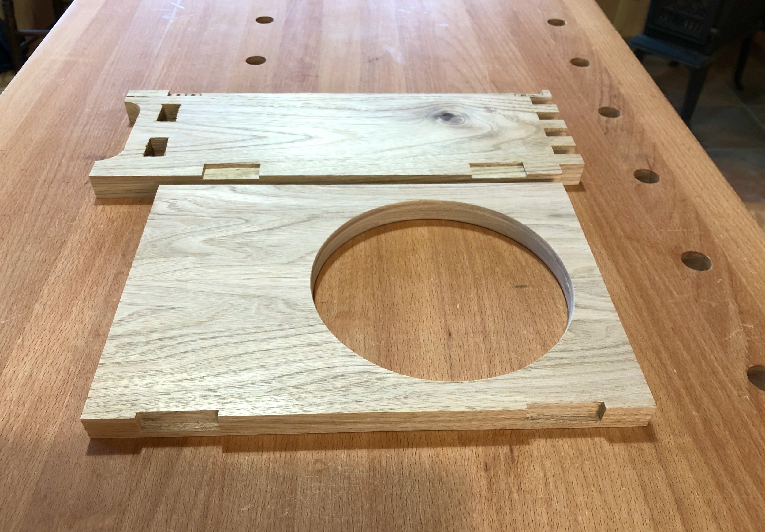
Door and case morticed to receive hinges
Assembly & Finish
After disassembling the dry-fit case and clock components (all the while making notes on the proper order for their re-assembly) it was finally time for glue-up. The mortice & tenon joints at the bottom were an ideal fit, but the finger joints up top were on the tight side and so glue was applied sparingly there for fear of swelling the wood prior to closure. Anyway, the case came together nice and square. Once the glue was dry the slight finger and tenon protuberances were all planed smooth and the case was sanded to 220 grit. Final sanding of the door and backboard were also conducted at this time. The plywood spacer board was then glued and screwed to the backboard and, with this piece tucked temporarily into the case, the four spacers for the clock face were attached to the case sides with glue. Dry-fitting the face board at this point revealed an unexpected challenge. The pendulum on this clock swings in front of the mechanism, and the hook at the end of the leader on which the pendulum mounts arches outward from the shaft just enough for this “highpoint” to rub along the interior of the newly mounted clock face. Routing out a slot, as for the suspension spring above, did not completely alleviate this friction source and so a 1/4 x 1 in. inch slit was cut out of the face to ensure the pendulum would swing freely. This slit is visible as a “feature” near the bottom of the dial, allowing a glimpse of the inner workings as the clock ticks away. Unplanned, but not unattractive.
On to the finishing steps. I liked the color of the butternut but would also be happy to see it darken over time. To assist the aging process, two applications of boiled linseed oil were applied (a 50/50 cut with mineral spirits, followed by a full strength coat) and after a couple days of curing, three coats of Arm-R-Seal wiping varnish were laid on over successive days. I used the satin sheen version of this product and find that it adds just enough life to the finish without tempting glare. The maple clock face, sanded to 400 grit, was finished with wiping varnish only. On test pieces I had played around with a couple dyes in the orange family. This color on the curly maple figure is stunning, but when placed behind the butternut door it made the clock appear disappointingly “artificial”. Good idea, but for some other Project.
A typical furniture piece would be complete right about now, but clocks are special; they need to both look good and also operate properly. The clock mechanism operates just fine as far as accurate gear movement is concerned, that was assured at the factory. Getting the gong right is the clockmaker’s job and involves two operations: aligning the hammer strike; and adjusting the minute hand. The hammer can only be aligned once all of the clock components are in their final position and so the movement was screwed to the backboard one final time and then held upright with a wood clamp while the pendulum and minute hand were affixed. To align the hammer, the thin steel rod supporting the head is bent/twisted, as required, to obtain a solid and squarely hit strike onto the outer ring of the metal gong. After aligning the strike I was able to adjust the length of the arm via a set screw on the head and then nip off the extra section of rod with wire cutters. A strong, stately gong every half-hour was the pay-off. Finally, the clock needed to be calibrated so that these gongs occurred whenever the minute hand was either straight up or straight down. This involves the iterative adjustment of a “square-holed” bushing nestled within the minute hand, itself, so that when pointed straight up it matches the rotational orientation of the square shaft when the gong hammer is released. A couple rounds of bushing twists followed by minute hand twirls and this clock was singing on the beat.
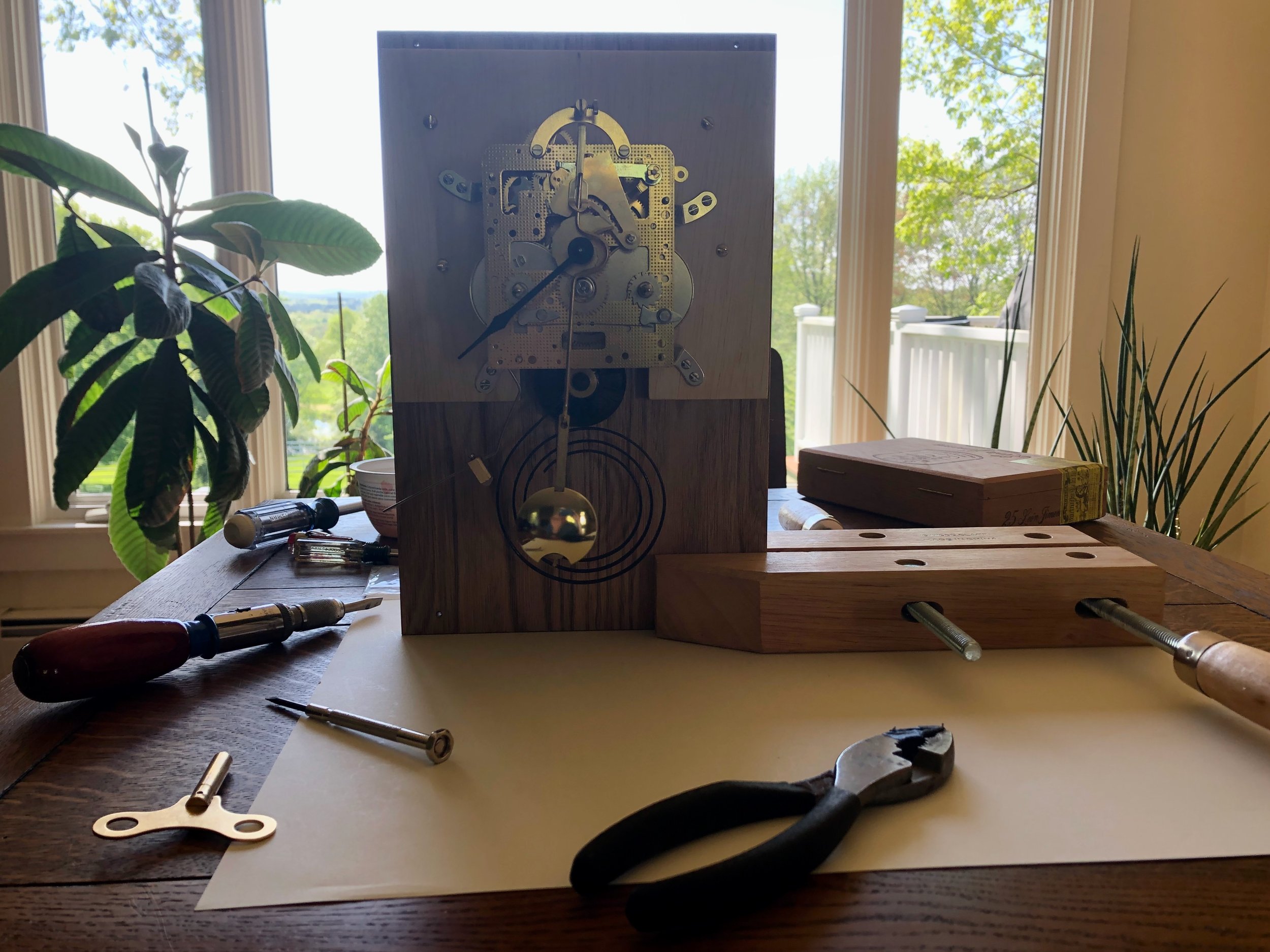
Adjusting the gong
The rest of the assembly proceeded as follows: mount the clock face with care to center the stem and arbors within their holes; press-in the brass grommets; attach the door hinges; mount the clock hands; and finally attach the pendulum. I chose to wait until this point to select and then mount the door knob. Torn between a wooden or a brass knob I collected a couple versions of each and then waited to get a feel for the finished clock, with the hopes that the choice would become obvious. Choice: brass. I liked how this material combined with that of the hinges and grommets to complete the exterior look and somehow suggest that there’s more brass to be found within. The knob’s mid-century design also kept things simple and round. A pleasing finishing touch.
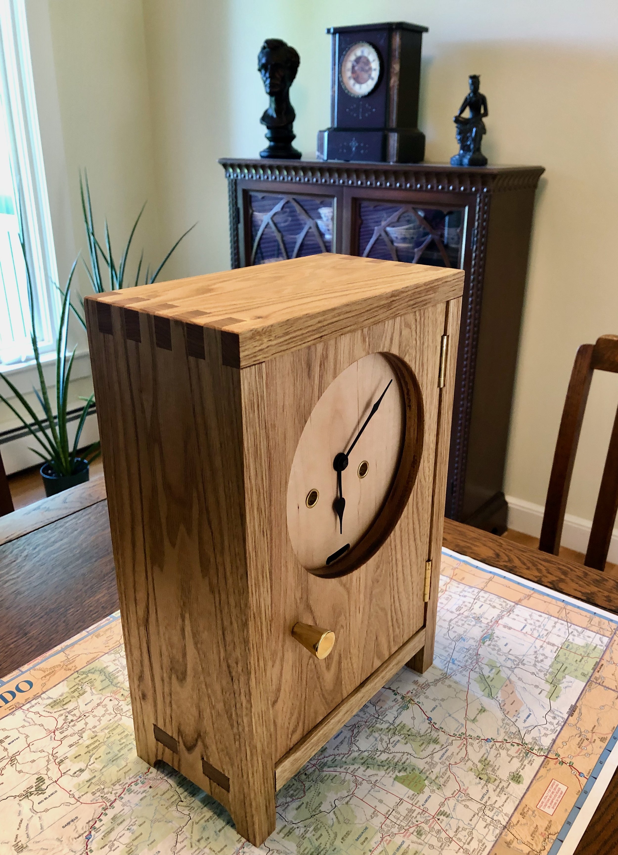
Clock of the Westies
Congratulations Julia and Spencer! Time to enjoy a wedding.
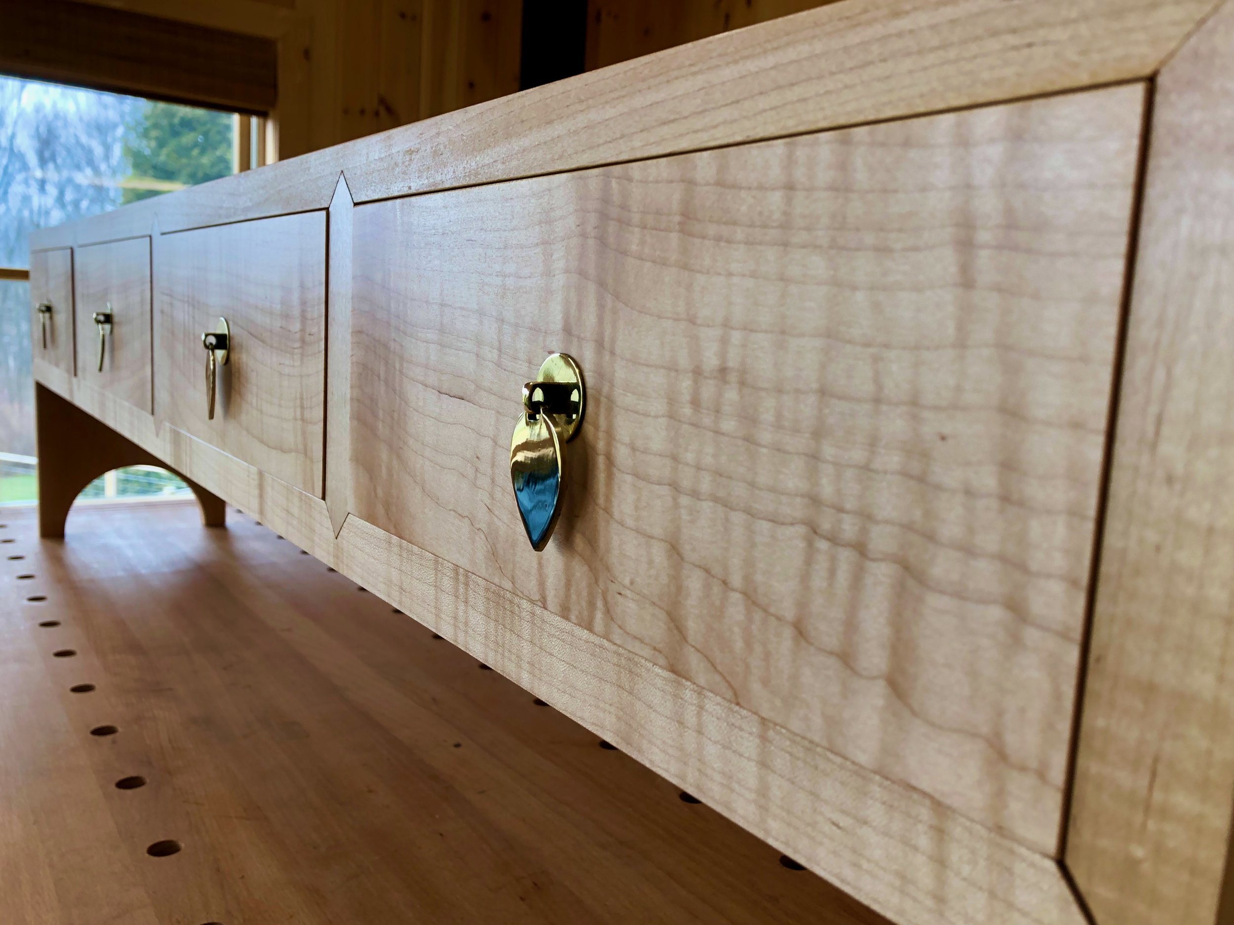
4 Drawers

Those of you following along from the early days will recall the Stationery Chest and might be wondering: “hey, what ever happened there?” Good question. The short answer is that, partially completed, it had been moved out of the workshop and was biding time in a spare bedroom while its maker tackled other Projects and gained experience. Those Projects have lulled and, fresh from a valuable tutorial in drawer building with the Ledger Chest, I was now anxious to finish off this piece and place it in our living room where it belonged. Here’s the story.
The carcass of this chest was completed in early 2021 following plans from a book on Korean furniture making. This Project was a good challenge for me, involving the rehabilitation of some beautiful but twisted curly maple lumber, as well as a foray into novel woodworking terrain, specifically the mitered dovetail and Korean swallowtail joints. The piece shows clear signs of not-yet-craftsman-like “craftsmanship” but I’m getting there. My hope is that a solid job on the drawers and some care with the finish will create a handsome and functional piece.
Design
The plan calls for “inset” drawers which is what will be made. The sliding mechanism for these drawers, not even contemplated until now, will be a platform created using small plywood boards affixed (out of sight) to the bottoms of the drawer partitions. Corner joinery is stipulated in the Korean language plans to be half-blind “fist” joints (aka dovetails) but here’s where I’ll go off-road. Never having made these joints before, I did not want to wade further(x4) into unexplored territory on this piece - it has seen enough already. It also turns out that, upon measurement, the drawer openings are “a tad askew” and that felt like trouble when trying to fit an uncompromising joint like the half-blind dovetail. In contrast, joinery used recently for the Ledger Chest drawers, the rabbeted half-dovetail, appeared to be forgiving in that dimension. It is a nice drawer joint and was the one selected here.
Note added in proof: I have looked up some old Korean cabinets in online auctions and have yet to find a dovetailed drawer - they are all butt jointed. Makes me think the literature contains revisionist methodology, but more research is required.
Materials
Aside from the maple carcass, we would need additional maple for the drawer fronts and some reasonable hardwood stock for the concealed drawer parts. While I had planned to use yellow poplar for the interior drawer components, I was “fresh out” of that wood. However, I did have a pile of “extra” hardwood scraps, accumulated over a couple years of project making. I decided to use some leftover African mahogany for the drawer sides. Why not? I came across a twisted mahogany board that would be difficult to work with as a furniture element but, re-sawn into thin planks and then chopped into 8 inch parts, this hard, well-behaved wood could serve nicely as drawer stock. Might be a good look, too. Baltic birch plywood would be used for the drawer bottoms.
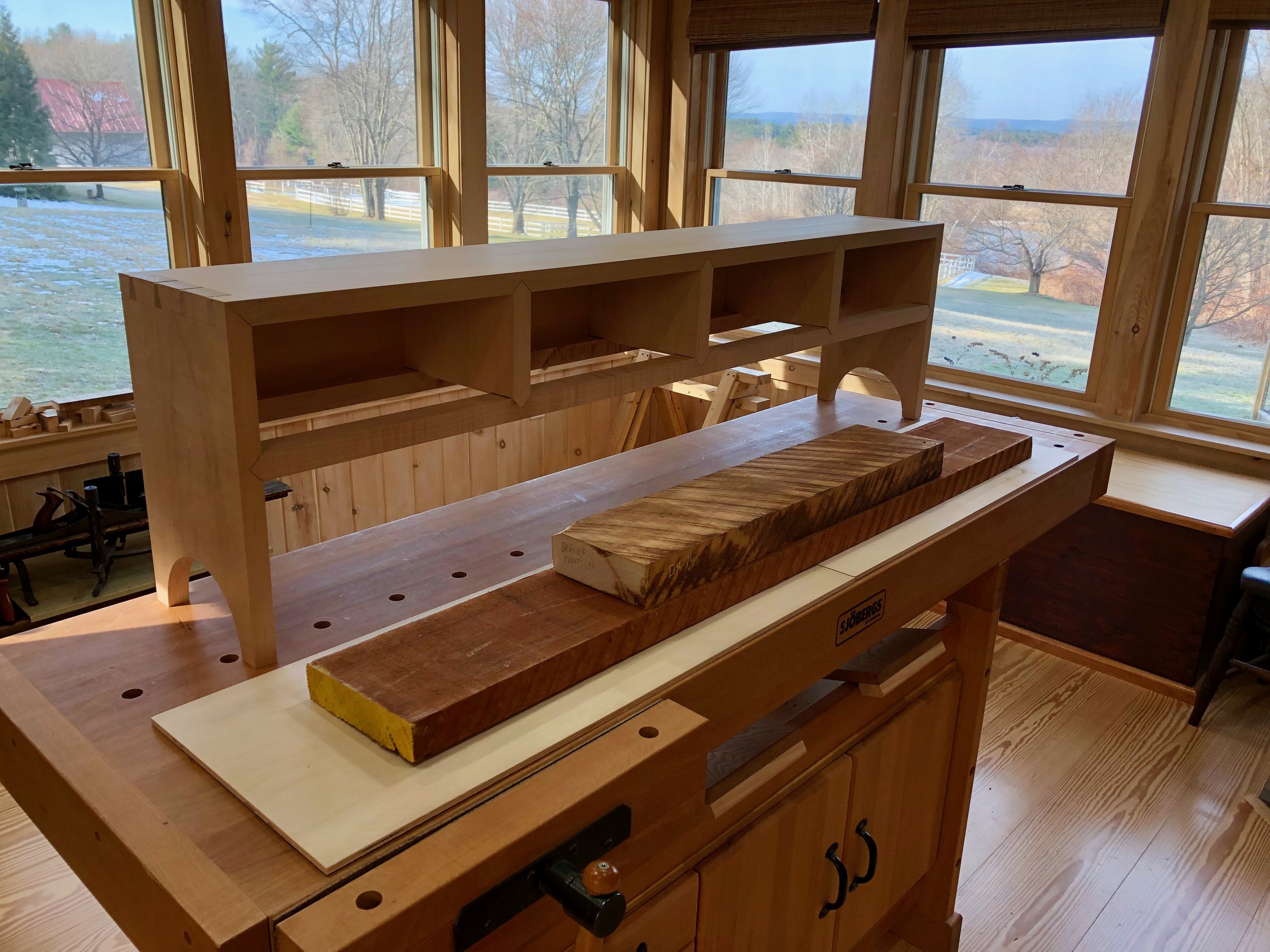
Wooden parts to complete the Stationery Chest
Consistent with Korean form, the drawer handles used would be single hooked, so-called “drop” pulls. These handles are quite unassuming compared with the hardware typically used to set-off (if not define) Korean furniture, but they should work well here where curly maple has the starring role. I found some Asian designs at a new online source for me, Ansaldi Furniture Hardware, which carries a wide selection of brasses. They seem solid and have just the right look. The design I had chosen for this chest is a variant of what Koreans call the “heavenly peach” and apparently this was the most commonly used handle for men’s stationery chests.
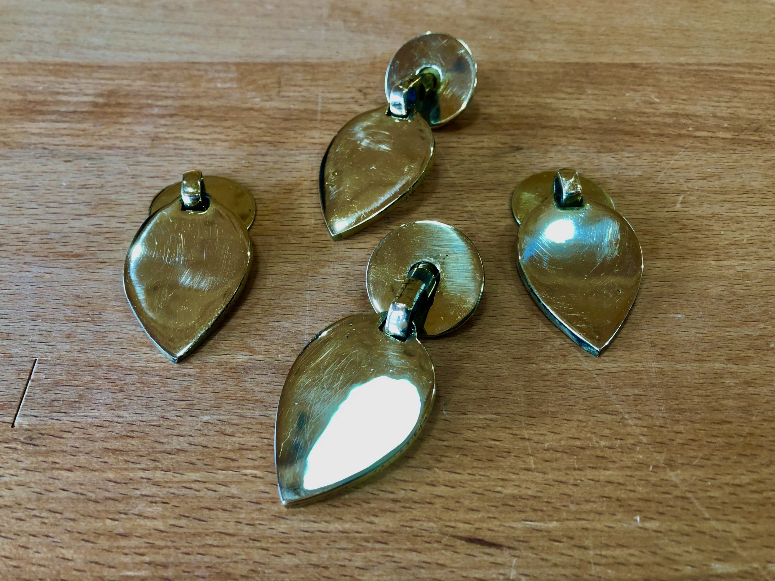
Heavenly Peach drawer pulls, in brass
Dimensioning
A piece of antique curly maple, the same as that used for the carcass, would form the drawer fronts. After removing decades of dusty accretions with a belt sander the 3 ft. long hunk was jointed flat on one edge, re-sawn into a pair of thinner planks and then jointed/thickness planed to a final width of 3/4 in. These beautiful boards will be used in a book matched orientation for the drawer fronts. (Although, since the pivot was on the short axis, it seemed more like “straight razor” matching.) To the extent that the finished grain shows its character, this should create an attention-grabbing, 56 inch flow across the entire front of the piece.
The drawer fronts were chopped to rough width, labelled 1-4, and then custom fit into their individual cavity openings. As mentioned previously, these openings were all about a degree off from 90 and so the sides of the drawer fronts needed to likewise conform with these slants. Now, hand planing along the end grain of wood is tricky business and so to create the new edge I found it easier to mark a line on the drawer front parallel to the cavity opening and then perform the angled cut along this line with the sliding miter saw. This saw comes equipped with a laser that casts a red beam directly below where the cut will occur. No need to measure angles, just align the laser with the pencil line and saw. I refer to this technique as “power fitting” and it may take a few centuries before it can be considered a traditional method. (Of course, by that time lasers are doing both the marking and the cutting, saw blades having become obsolete.) Anyway, it works pretty well today and it rapidly facilitated the nesting of all four drawer fronts.


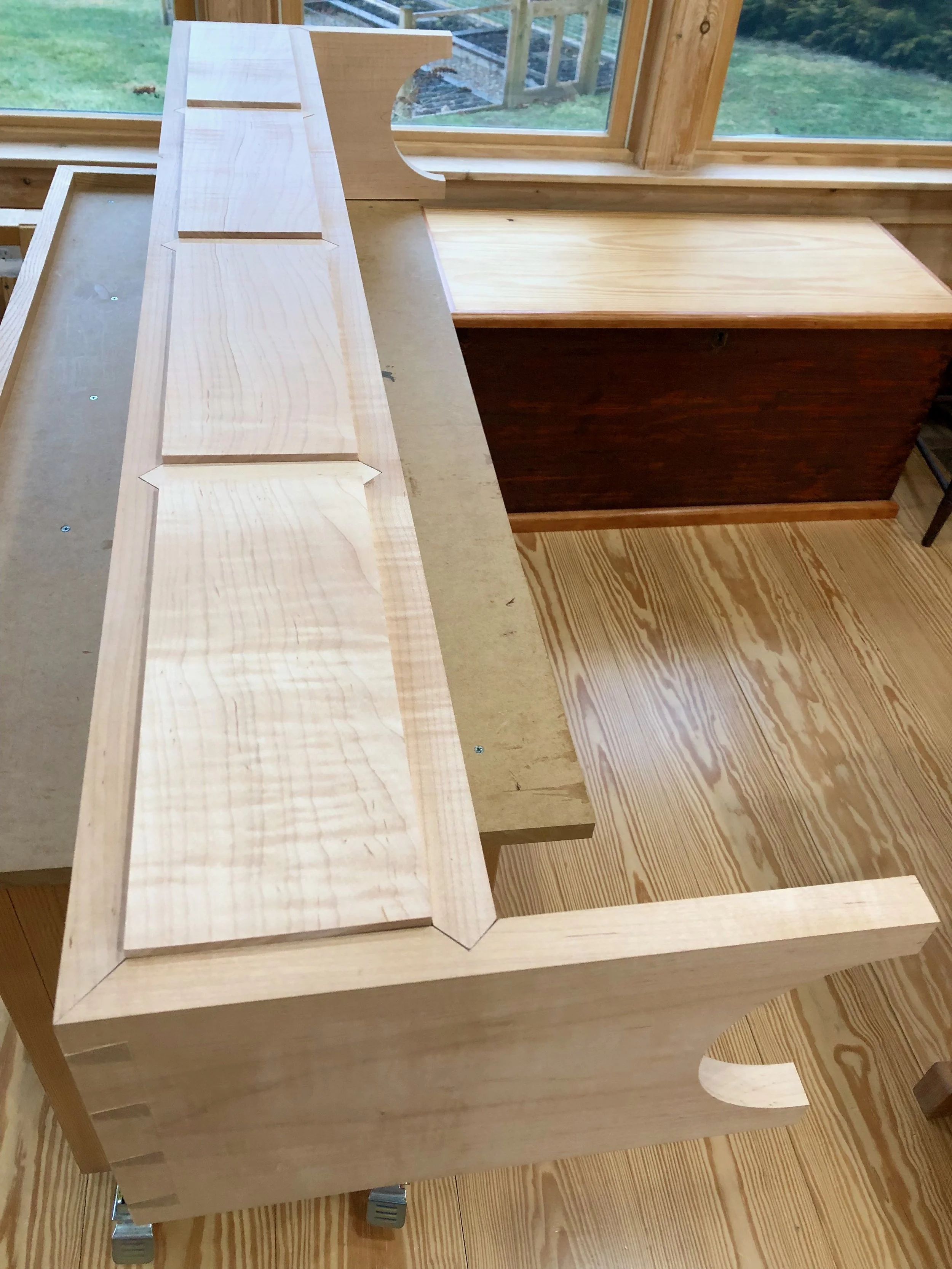
Drawer fronts fitted to their cavities
Next, I needed to create the sides, backs and bottoms of the drawers - 16 pieces, in all. This was done essentially as described for the Ledger Chest in episode 2 and need not to be recorded here. However, I did make one improvement worth noting. The half dovetail cut at the router table for the side pieces involves a vertical board orientation, where the end grain is slid along the table’s surface as the cut is occurring (illustrated below). That “surface”, surrounding the router bit spinning @ 23,000 rpm, is made up of a melamine table top, aluminum router plate and a circular plastic collar. As these materials do not abut smoothly, the resulting bumps, even though minuscule, are enough to make for a troublesome cut and a rough looking result. To eliminate this source of imperfection, I fashioned an auxiliary table top out of a small piece of dry erase board stock which allowed the mahogany boards to slide through the cutting bit with ease. Good solution with many more applications to come!
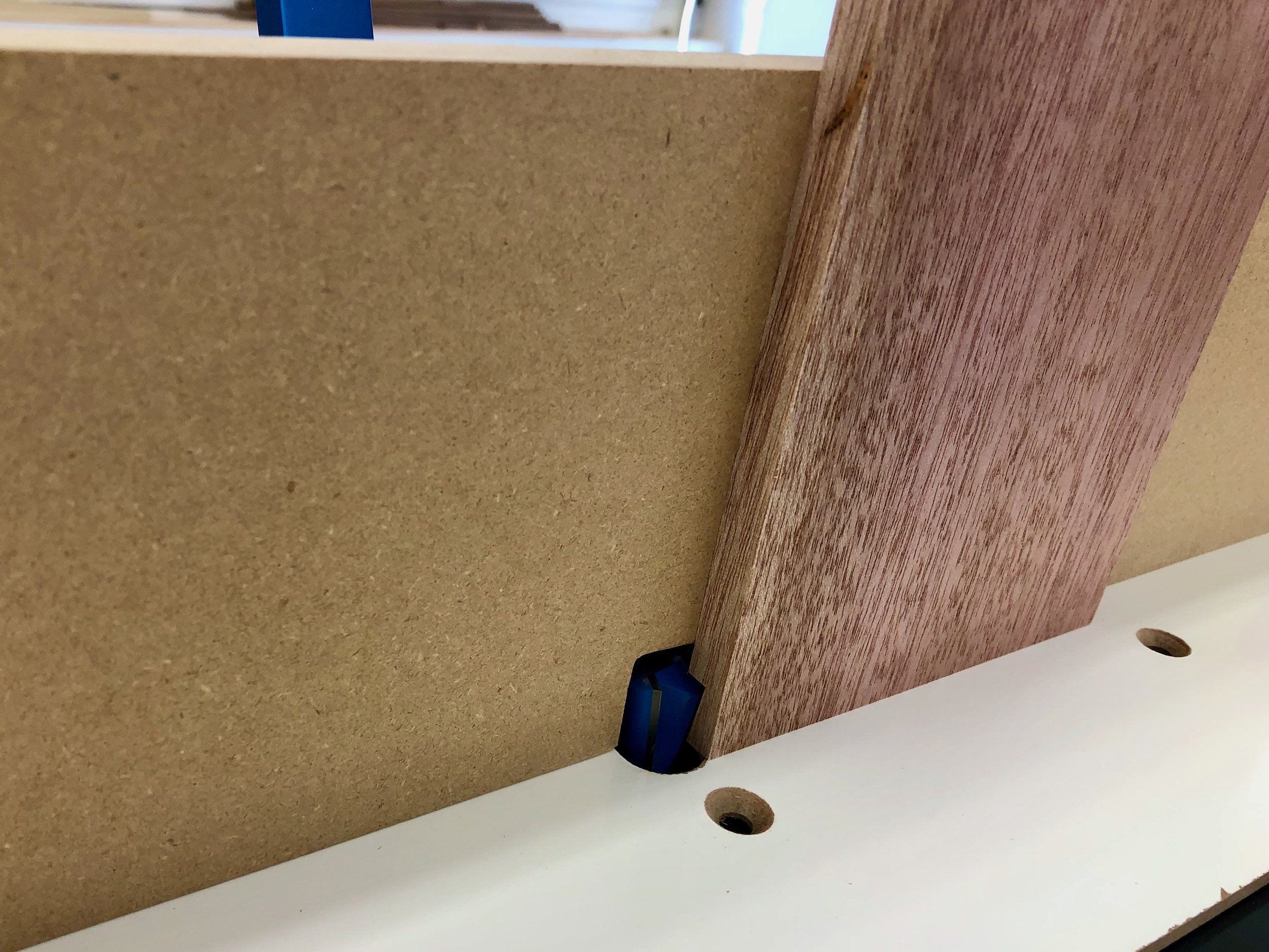
Mahogany drawer side being cut by a dovetail bit while sliding on the white auxiliary table top
Assembly & Finish
With a few hand plane strokes and some sanding, the labelled, dry-fit drawer constructs were methodically “futzed” into their cavities until they all operated as intended and a reasonably uniform gap pattern was achieved along all of the edges. The drawers were then disassembled and re-assembled with glue and clamps. Once dried, hardwood dowels were used to pin the front corner joints and the sides were then re-sanded smooth.

Fully assembled drawers
Finally, the carcass needed to be finished. That started with addressing the dovetails. The end grain portions of both the pins and tails stood somewhat “proud” of the joined surfaces (oh well, at least one of us was proud). While not uncommon in this type of joint, these protrusions would need to be leveled prior to the final sanding. Cutting lightly with a sharp block plane, they were slowly whittled down to “flat”. The sides and top were then smoothed with an orbital sander, progressing through a 120/150/220/400 grit sequence to make it look shiny-clean. Next I tried a technique for finishing “inset” drawer fronts that I read about in the handy reference book Building Doors & Drawers by Andy Rae. To begin, the carcass was flipped onto its back and small felt pads were affixed to the backside of the cabinet interior. These pads touched the rear of the drawers so that when fully inserted their faces peeked just proud of the frame. Sighting down the surface now reveals the topographic undulations of drawer front and frame elements which would be corrected in the following manner. The drawers were wedged tight within their opening using softwood shims and then the entire surface was worked carefully with the orbital sander using a 150/220/400 grit progression. Once everything was smoothed to satisfaction the shims were knocked through to liberate the drawers. Not perfect, but much better than the original state. The empty carcass was then flipped upright and all of the right-angled edges were “broken” using sandpaper to achieve a soft feel while retaining a sharp look.
The final step was to apply the finish. I had experimented earlier on a sample board where portions were first treated with either: 1. de-waxed shellac; 2. linseed oil; or 3. wiping varnish, followed by two coats of wiping varnish over all sections. It seemed the curly maple grain was highlighted nicely in every case, with the linseed oiled portion taking on a noticeably oranger hue compared with the others. Over time, that oiled portion would likely darken faster than the other two segments but that was not my goal on this piece. I was seeking to do right by the curly wave patterns in the wood and it looked like the Arm R Seal wiping varnish beat-out the shellac in this instance. Three coats of wiping varnish were then applied, with some minimal sanding in between and a buff job at the end, to finish the wood. Installation of the heavenly peach drawer pulls at last completed the Korean Stationery Chest, a good learning Project for me and a fine addition to our living space.

