

Square Rose Tribute

Chauncey Jerome
American clockmaker (1793-1868)
Allow me to explain …
It all starts with the nineteenth century American clockmaker, Chauncey Jerome. His is a remarkable story of unrivaled success shattered suddenly by financial ruin. Alas, such was life before the social and regulatory “safety net” age that we enjoy today. Working in pre-Industrial Revolution America, Jerome is recognized as a pioneer of modern clockmaking. He began on the trail blazed by his former boss, Eli Terry, as an early mass producer of clock cases, using water wheel-driven saws to cut his boards. Attempting to further improve the affordability of his wares he went on to invent a method for stamping-out clock parts from brass plate that replaced the use of wooden or cast metal gears. Remembered more today for his casework, it was the technological advance of using brass plate, along with ingenuity and hard work, that propelled the Jerome Manufacturing Co. at mid-century into “the largest clock manufacturing operation in the world”*. Jerome’s business was at its peak in 1854 when he was elected the mayor of New Haven, Connecticut. But within a year, following a cascade of poor business decisions, rooted in the chicanery of one P.T. Barnum, he was wiped-out financially. And his wife, Salome, also died. Upon losing the business, Chauncey Jerome went on to work with a few other clock companies which only served to drain his remaining wealth and he died penniless in 1868.
* Bailey, C.H. From Rags to Riches to Rags: The Story of Chauncey Jerome, NAWCC BULLETIN Supplement #15, Spring, 1986, p. 101.
Fortunately for our story, Chauncey’s son, Samuel Bryan Jerome, continued the clockmaking tradition and even went on to gain a few U.S. design patents for clock cases. One such design, patented in 1857, was for a handsome shelf clock produced by the Waterbury Clock Co. that became known as the Square Rose.

Oct 20, 1857 design patent for the Square Rose.
Unless you are into clocks, this drawing might not look like anything special. There were clock cases aplenty during the golden age of timepieces, many more ornate than this one. You can still find these at antique stores and on eBay, where it will become evident that not all designs hold their attraction over decades of changing tastes. I think that is where the Square Rose shines. Its particular combination of wood, moldings and painted glass still gives pleasure, today. Perhaps it is the proportions more than the components but, whatever the allure, I felt compelled to make my version. It will serve as a heartfelt gift to my niece Lauren and her beau Travis on the occasion of their wedding, and also as a small tribute to clockmaker Chauncey Jerome.
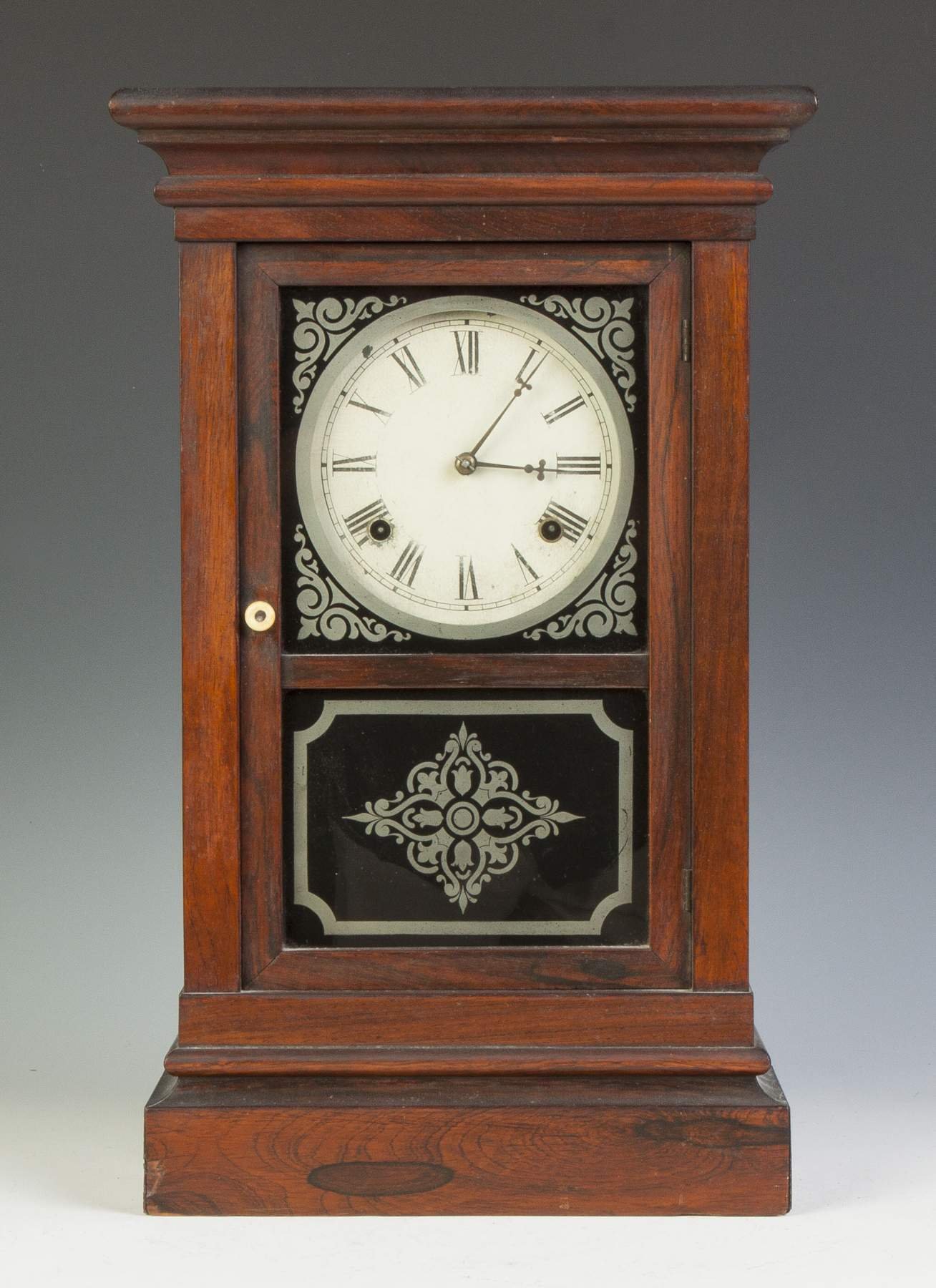
Square Rose, 30 hour, spring-driven clock c. 1860. reproduced from Cottone Auctions website
Design
Most of what I have learned about this clock comes from the website of an enthusiastic Jerome collector named Mike Bailey. From pictures of his clocks, and others found on the internet, I have a good idea of the shape and proportions of this 20 1/2 inch tall case. The above photo enabled me to divine the dimensions sufficiently to produce my own working plan which was scaled-down to a 19 1/2 inch height to best accommodate the dimensions of the dial I purchased while maintaining the original’s proportions. The case is essentially a box decorated with moldings, the specifications of which make up the bulk of that 1857 U.S. patent. This three page, handwritten document is packed with the precisely vague legal vernacular that would be further perfected during creation of the 10+ million U.S. patents to follow. However, even these descriptions were no match for actual photos and measured profiles generously provided by Mr. Bailey via email correspondence. These were invaluable to me for creating a construction strategy. Thanks Mike!

Three-part molding profiles of an extant 8 day Square Rose clock case, courtesy of Mike Bailey
Even supplied with this information, the exact dimensions of every feature, as well as the construction plan of my clock case would differ from the original. That speaks more to how a modern furniture maker builds a single case, as opposed to a mid-nineteenth century factory trying to turn out thousands. But, since there’s more than one way to do everything, I think that’s okay. After all, I am not trying to reproduce the article, just the article’s presence. Here is how the dimensions were gleaned from the original picture.
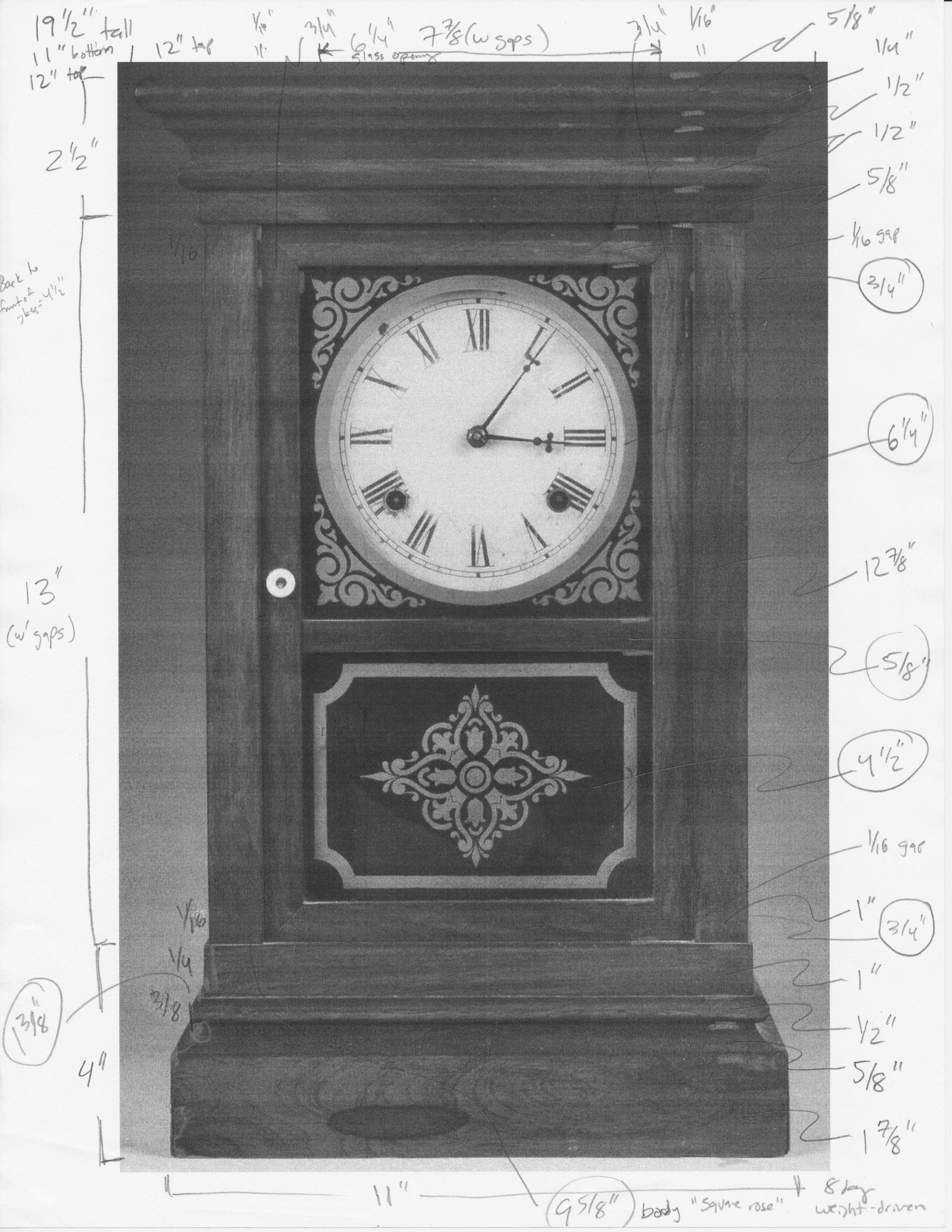
Every feature measured and then scaled-up from a photo printout
And here is the working plan derived from these numbers.

Construction plan (front view)
Materials
I believe the example above was made of rosewood, an exotic species now banned for commercial use, and I have seen other examples that appear to be made from walnut, but I should do more research. Anyway, I would like to make this one from cherry. I found a brightly figured 8 foot long, 4/4 board at the lumberyard that looked perfect.
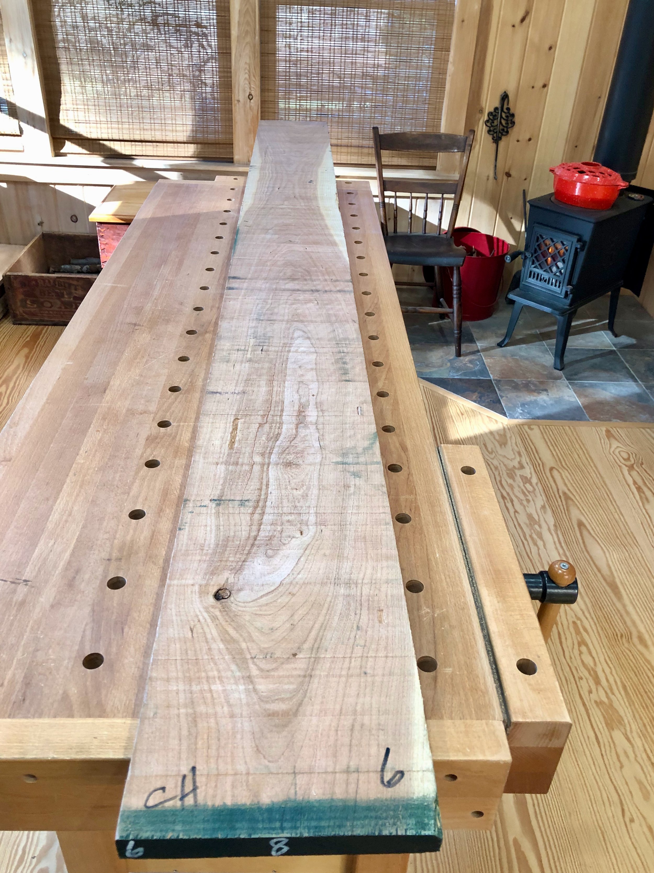
Cherry board
The clock parts were ordered from Clockworks, my favorite supply store for good reason: they partner with you to ensure customer satisfaction. On this occasion, because I was ordering both the mechanism and the dial, I also took advantage of their dial drilling service to get the arbor holes “right” while losing not a wink of sleep in the process. The remaining components (glass, hinges, nuts, bolts, screws and a knob) were procured from local stores and Etsy during the build.
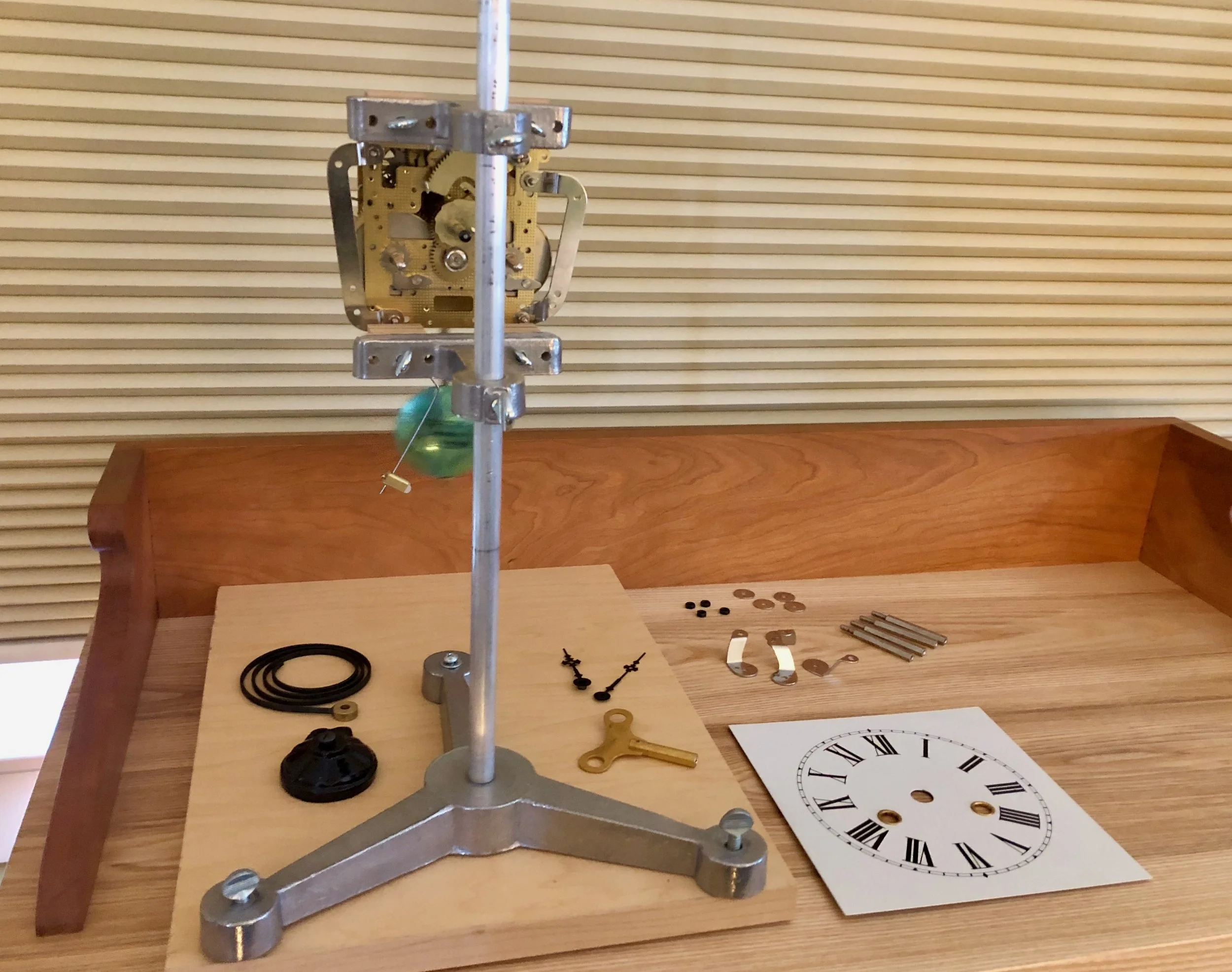
Clock parts and mounting hardware
Dimensioning & Assembly
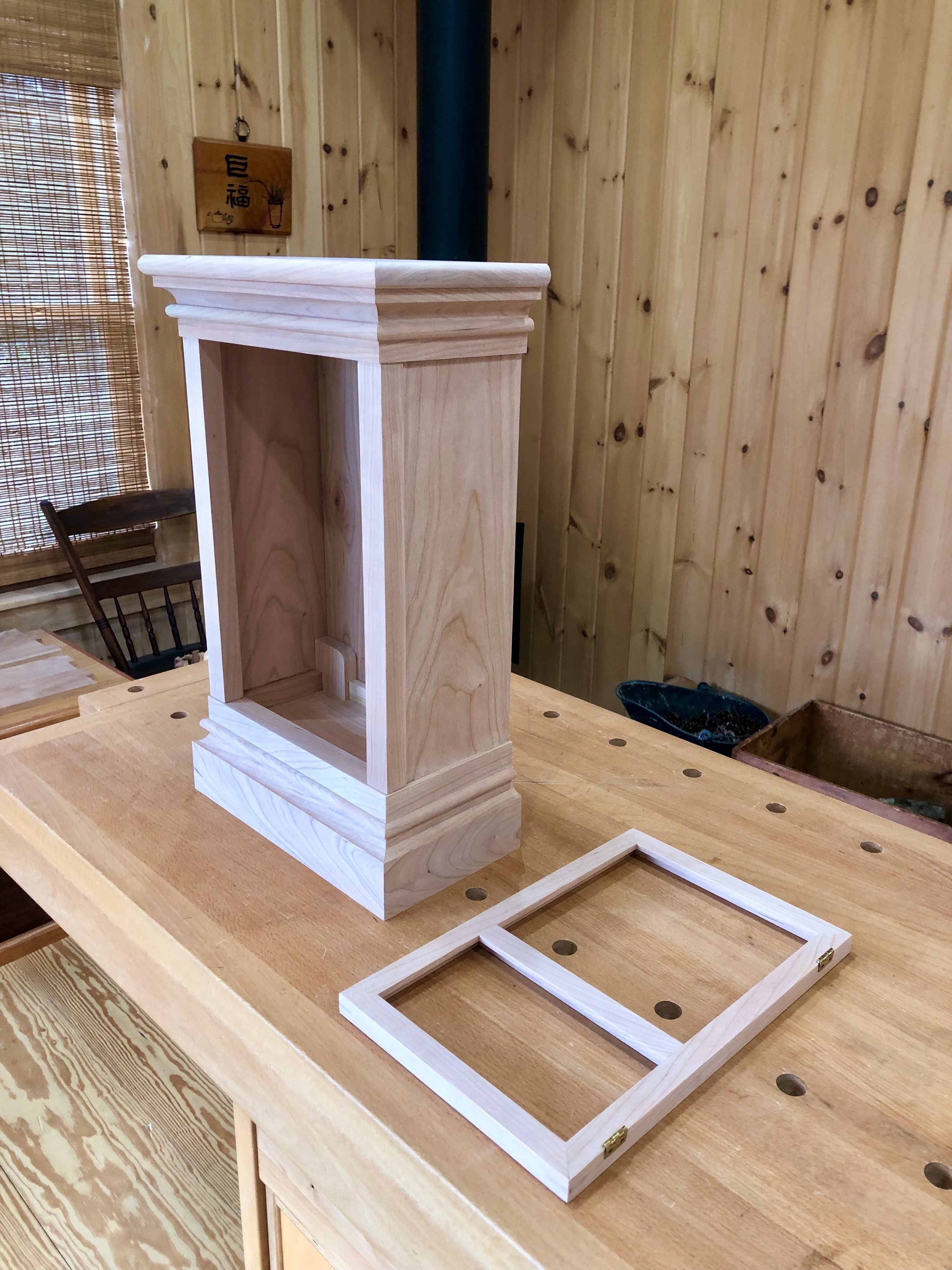
Before tearing into the cherry board, I used some scraps to practice molding-making, as well as the general construction plan. Those elements above and below the door, referred to henceforth as “top” and “bottom”, were the subject here. Although these layers of the original were individually crafted, as evidenced by Bailey’s photos, my intention was to use the same 3-component strategy to build both the top and bottom portions of the case. Parts A, B & C, which differ in dimensions (top vs bottom) would otherwise be created in an identical manner in the workshop. For simplicity, the description below will focus on just the bottom portion and sprinkle-in some of the patent terminology for effect. My plan called for a plinth (part A, see below) to provide both mass and a bottom frame element for the door. For this clock, a groove cut into the backside of A would also support the case floor. Covering most of part A will be an outer panel (B) possessing beautifully figured grain and a cove cut-out along the top to serve as both the wreathing and quirk elements described in the patent. The seam where parts A and B meet will be augmented by a semicircular astragal component (C). In an inverted fashion, the top would contain these same elements and be crested by a full board covering the entire case. To provide better orientation, a model of the bottom portion is shown below.

Dry-fit model of the case bottom showing association of parts A, B and C.
With the construction plan validated I could mark-up the cherry board, selecting ‘which portions to use for what’. Surprisingly, this clock case would consume the entire 6 board-feet of material!

Board marked-up “butcher style” prior to making the first slice
The material was sectioned accordingly and the individual molding components milled to their proper dimensions using tools in the machine room. The transformation of raw wood into purposely designed parts never loses its appeal, and the scale of constructing clock cases makes this process particularly intimate. Without documenting every step I provide a few glimpses below.
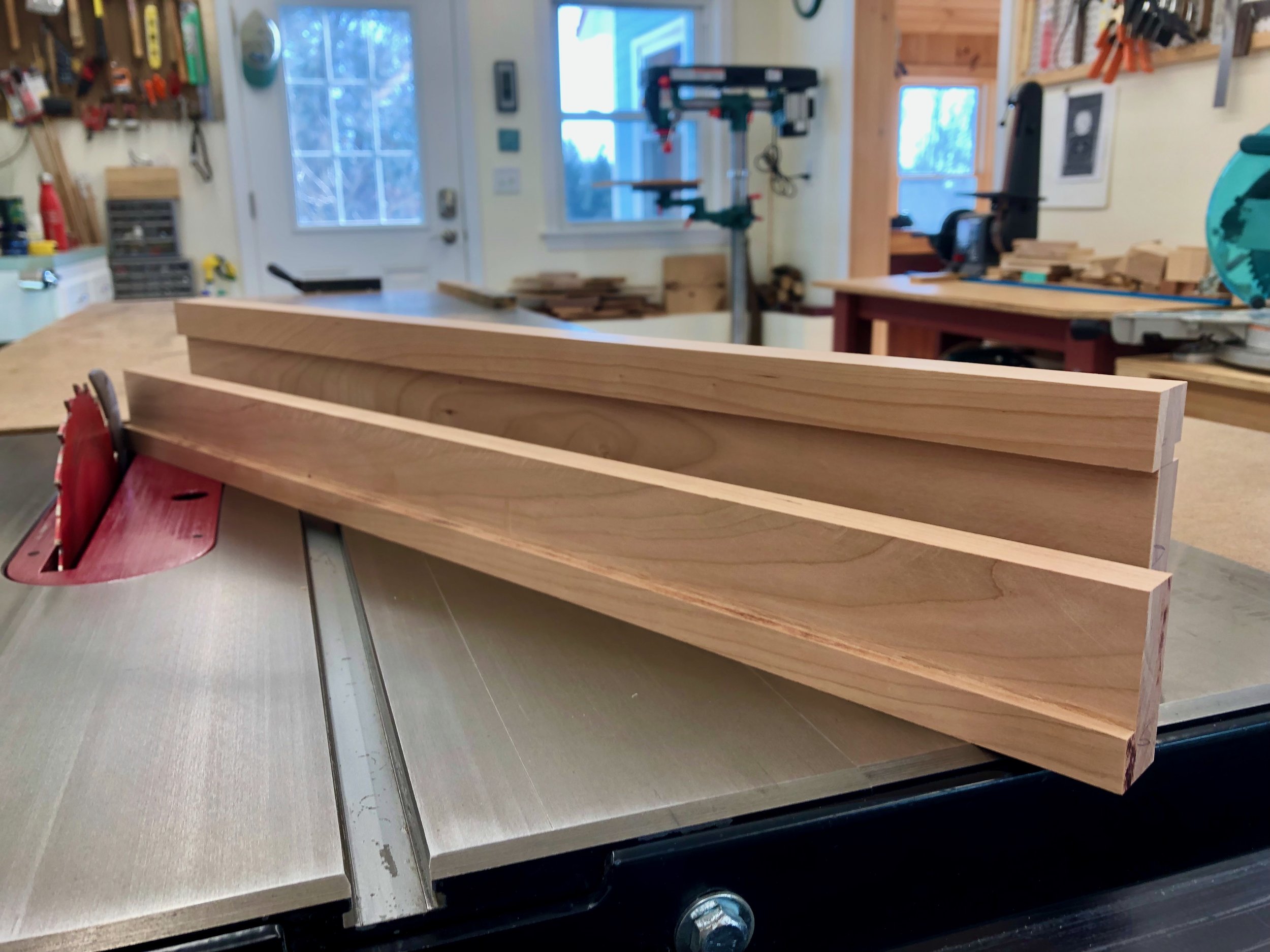
Molding parts “A” prepared at the table saw

Cutting a cove on the “B” moldings at the router table

Four passes with a round-over bit (router) and four with a dado blade (table saw) prepare the “C” molding stock

C moldings were cut free at the table saw and then hand planed to trim the parts
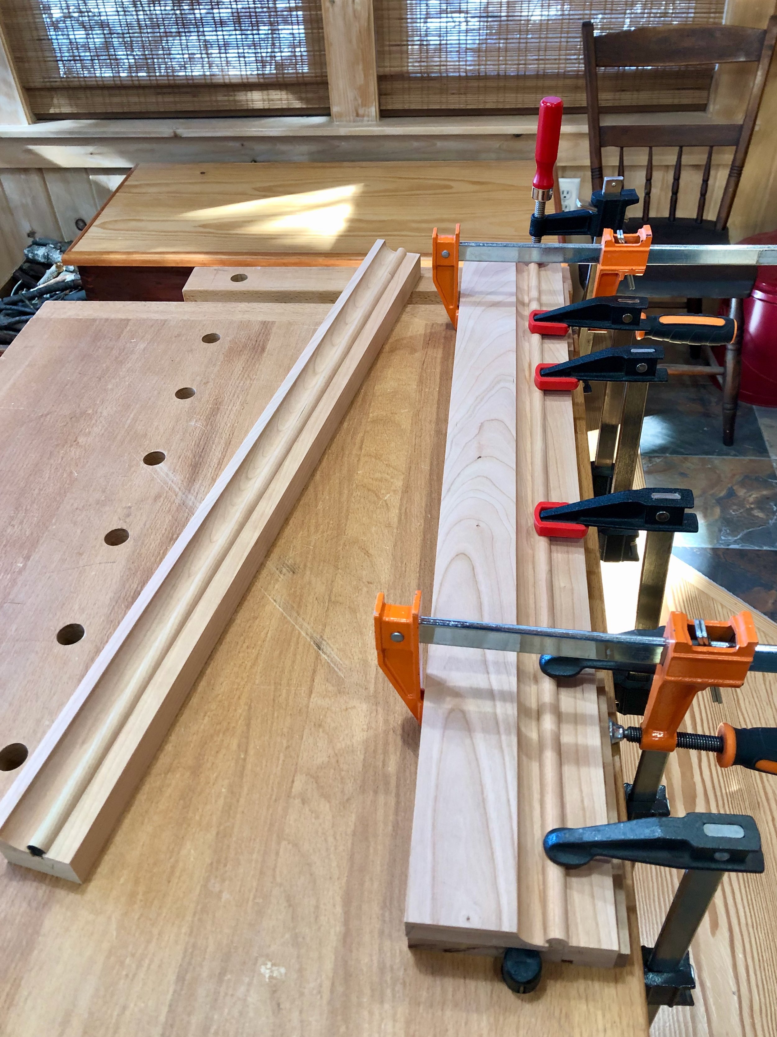
Glue-up for the bottom section, top section complete
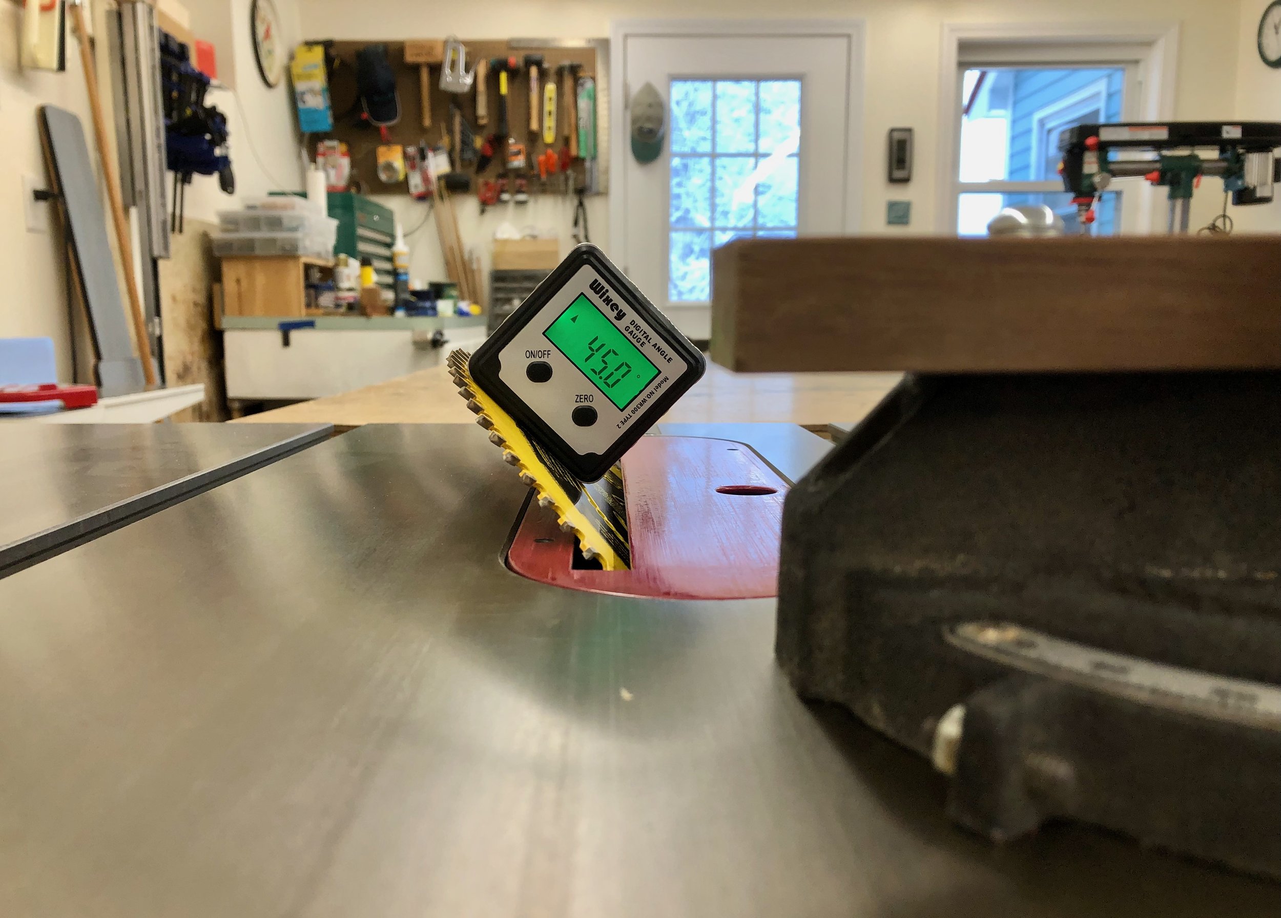
With stock for the components in hand it was time to create the mitered joints. For this I used a finishing blade on the table saw, tilted at 45°. During the cuts I used a sacrificial backing board on the miter gauge and some painter’s tape on the astragal to avoid tear-out. I then dadoed grooves into these pieces to house the case floor and sides.
Prepping for the miter cuts
From here it was a matter of fashioning the rest of the parts, cutting to rough lengths, fitting grooves and matching thicknesses. I eventually needed to establish a final case depth, and this required the mechanism. Still without a clear plan for how the clockworks would be mounted within the case, at this point I simply needed to be sure the cavity would be large enough to accommodate them, keep the hands clear of the door and allow the the gong to strike. I settled on an interior depth of 4 1/2 in. and a height of 14 in. which was close to the original design plan.

Sizing up the cavity’s depth and height
With these dimensions fixed I could complete the remaining case parts, cut the side moldings on top and bottom to final length, and create the back. To ensure a stable construct I inserted splines in the miter joints of the top molding assembly, whereas the bottom section would rely on the enclosed floor board and some corner blocks for support. The parts all came together nicely in a partially glued state.

Dry-fit case
I chose not to complete the case glue-up until I had a chance to drill holes into the door frame for the hinge screws. At this stage all I needed was a tight and square assembly so that I could take some final measurements and fashion the inset door. I made the mitered joints for the door at the table saw, but this time with the blade at 90° and with the assistance of a picture frame jig built a few years back by my son Andrew. When picture framing, it does no good to cut a true 45° miter if you cannot also guarantee that the paired horizontal and vertical members are identical to one another in length. That is where this jig excels. After creating rabbets on their backsides to house the glass, the four frame parts were individually mounted onto the jig and cut to final dimension at 45°.

Making an accurate and reproducible “length cut” at the table saw using a picture frame jig
Into the righthand stile I chiseled mortises for the hinges. The “door”, indistinguishable from a picture frame at this point, was then glued-up using a band clamp. To further stabilize the corner joints, splines were inserted with assistance from another jig at the router table. I then cut the door’s central muntin to length at the miter saw, and made rabbets for the glass at the table saw. Finally, this part was secured in place with a couple small wooden dowels that began their career as toothpicks.
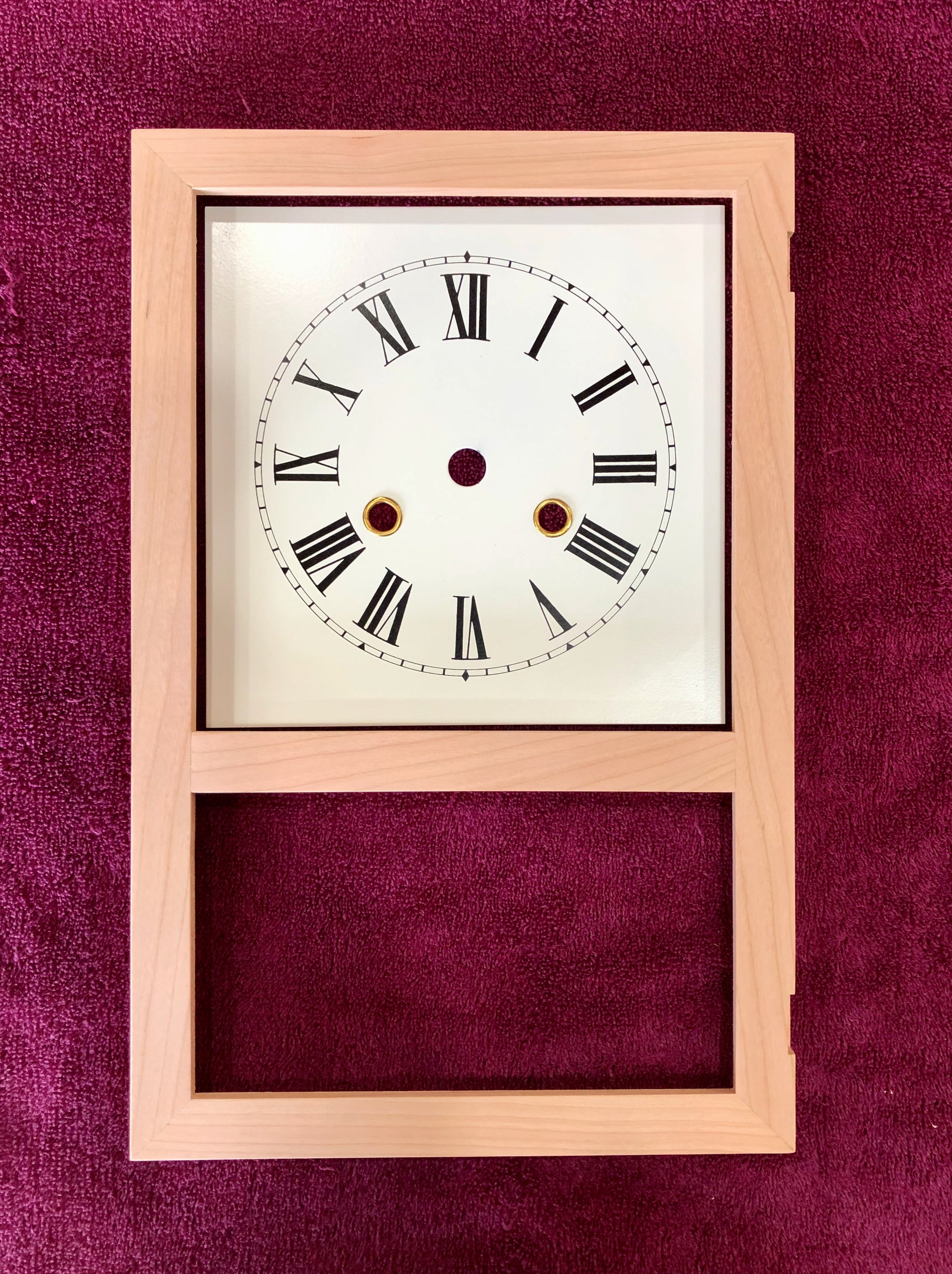
Completed door laid atop the clock face
The last thing to do before glueing the case was to mount the door hinges. After drilling holes in the door and fastening the hinges with screws I applied double stick tape to the remaining hinge plates and then, with spacers beneath, slid the door sideways within the dry-fit case opening until the plates were stuck to the frame. The frame piece and door were further wrapped with painter’s tape then carefully disassembled from the case. “Opening” the door revealed the exact position to drill the screw holes there. A new assistant showed up while I was about to photograph this step, and stayed to help complete the task.

Hinging the door with “help” from granddaughter
I could now glue the door frame and sides to the top and bottom portions of the case. Then, following installation of some bracing blocks, the back was cut to final dimensions and installed with screws. That left the top as the only remaining case part. This element was not present in the original, for what looks to be a “top” there is actually a feature of the molding that surrounds a false top within, but I prefer the real thing. To make it, I thickness planed a beautifully figured cherry board to 5/8 in., cut it to final dimensions and then rounded three edges at the router table. It will be attached using desktop fasteners during final assembly.
Completed cabinet and door
While the case is distinctive, to me the Square Rose is defined by the ornamented glass that surrounds the dial ring (called “spandrels”) and decorates the lower pane (the “tablet”). According to Bailey, these would have been created on the original using a printing transfer technique called “decalcomania”, with the surrounding field painted afterwards. I chose a twenty-first century method to decorate my glass: vinyl cutting. And to pull this off I solicited the assistance of my sister-in-law, Chris (aka mother of the bride). Crafting with cut vinyl is one of the many creative talents Chris executes with great skill. For this clock she was able to extract patterns from that photo of the original shown above, correct their imperfections(!) on the computer, scale the dimensions appropriately to fit a photocopy of the dial, input the coordinates into her machine and then create exact vinyl replicas for this clock. (I wonder if anybody has done this before?) The gold colored vinyl designs were carefully applied to the interiors of two glass panels which she then spray painted over in black. And they looked perfect!
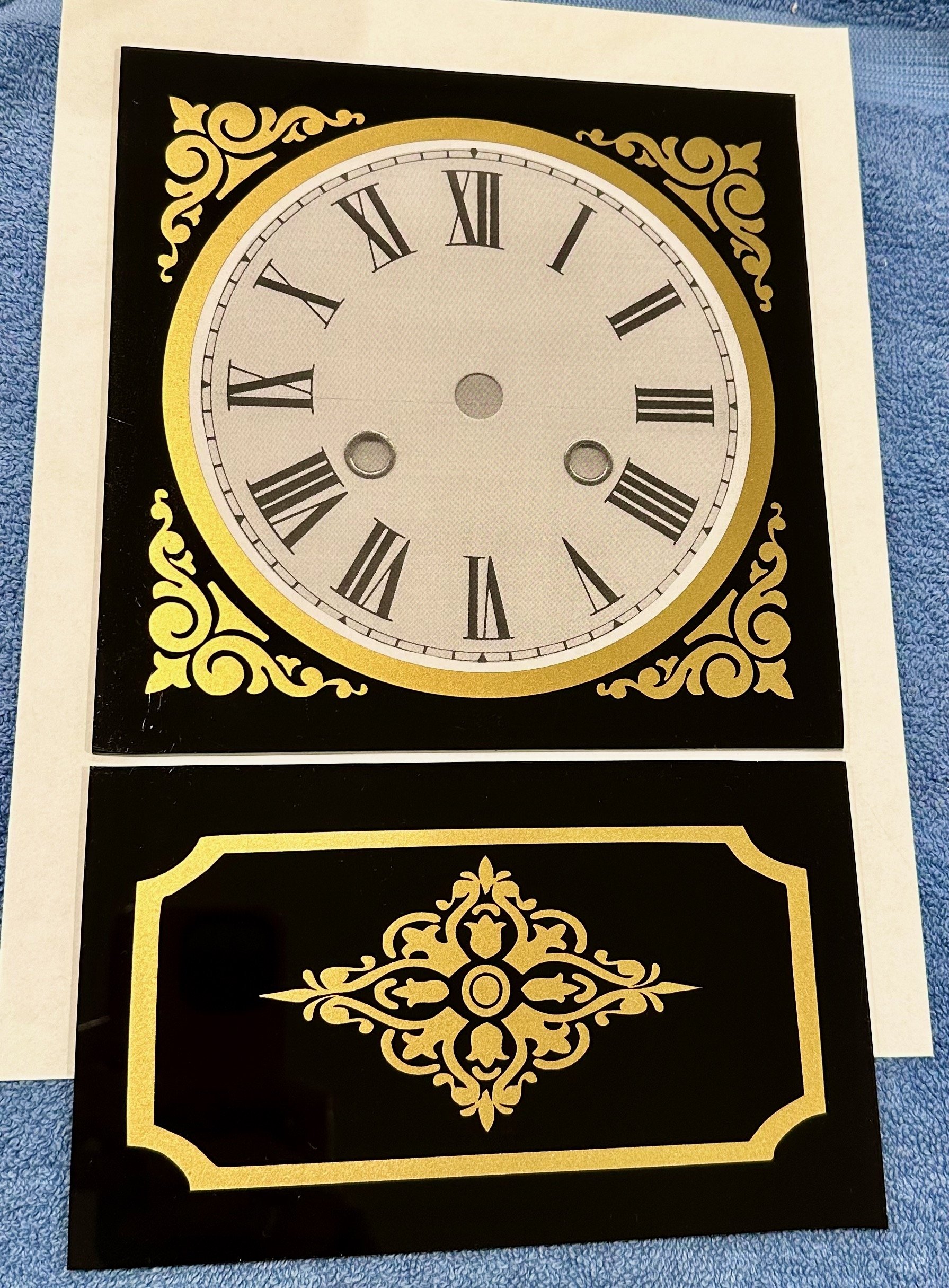
Glass art
Finish & Final Assembly
In the meantime, I was able to finish the cherry wood and prepare for mounting the mechanism. With the top, door and back removed, the parts were sanded uniformly to #220 grit and then finished using two applications of satin gel polyurethane. This livened the grain and left the surface with a nice touch. Once the glass panels arrived, they was inserted into their panes and held there by thin cherry backing boards.
Mounting the works was the final challenge, made a bit more difficult by my choice of a rear pendulum placement. The Hermle movement used for this clock is not like the Waterbury original, nevertheless, its a fine machine and close enough for our purposes. (I need to get more experience with the various movement configurations.) The issue with this one is that the gong strikes below the works and, as such, a front pendulum version would have been best for ease of access. Undaunted, I found that by mounting the works to the back of the case and inserting a small wooden block to hold the gong base, I was able to make it all work. Here’s how it went.
The metal clock dial was first secured to a 3/8 in. thick plywood board attached to the front of the works. Then, with the case laid prone on the workbench, the movement was positioned so that the time track on the face was centered within the vinyl ring on the door glass. Held in this position, the mounting brackets at the rear of the movement were fastened to cleats on the back of the case using screws. Next, the back was removed and the gong parts installed.
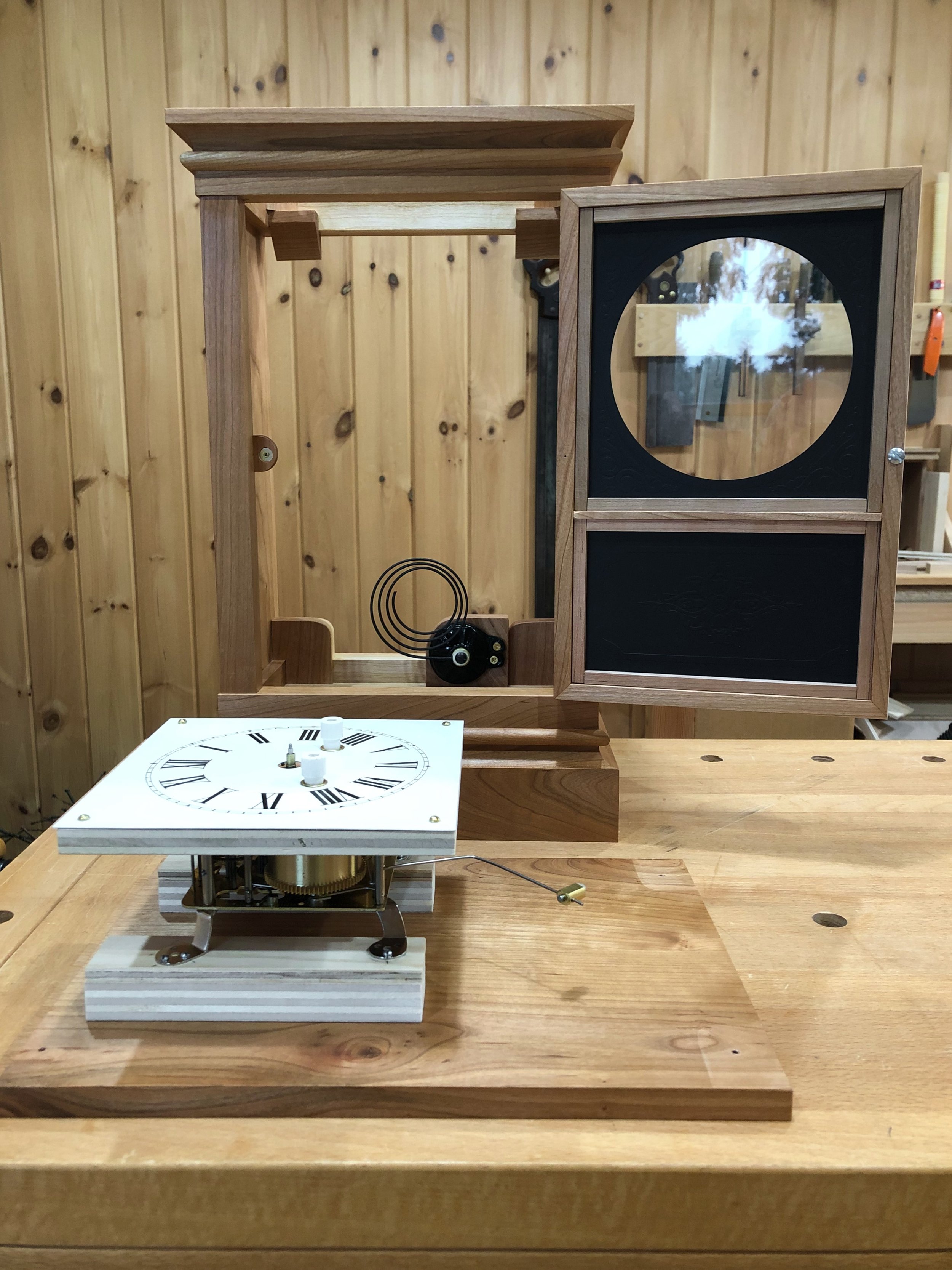
Movement and gong mounted
Finally, the top was affixed and the back re-attached to the body. Everything fits. Accessing the pendulum is perhaps trickier than it should be but, on the plus side, the strike sounds beautiful!

Works and top in place.
No matter the location, it’s always a “destination” wedding if you are a gift clock. This one needed to find its way from Massachusetts to Wisconsin for the ceremony and, ultimately, on to Iowa for its final perch. I have always used my carry-on luggage for transport and, fortunately, there was one old bag in the basement large enough to serve that purpose.
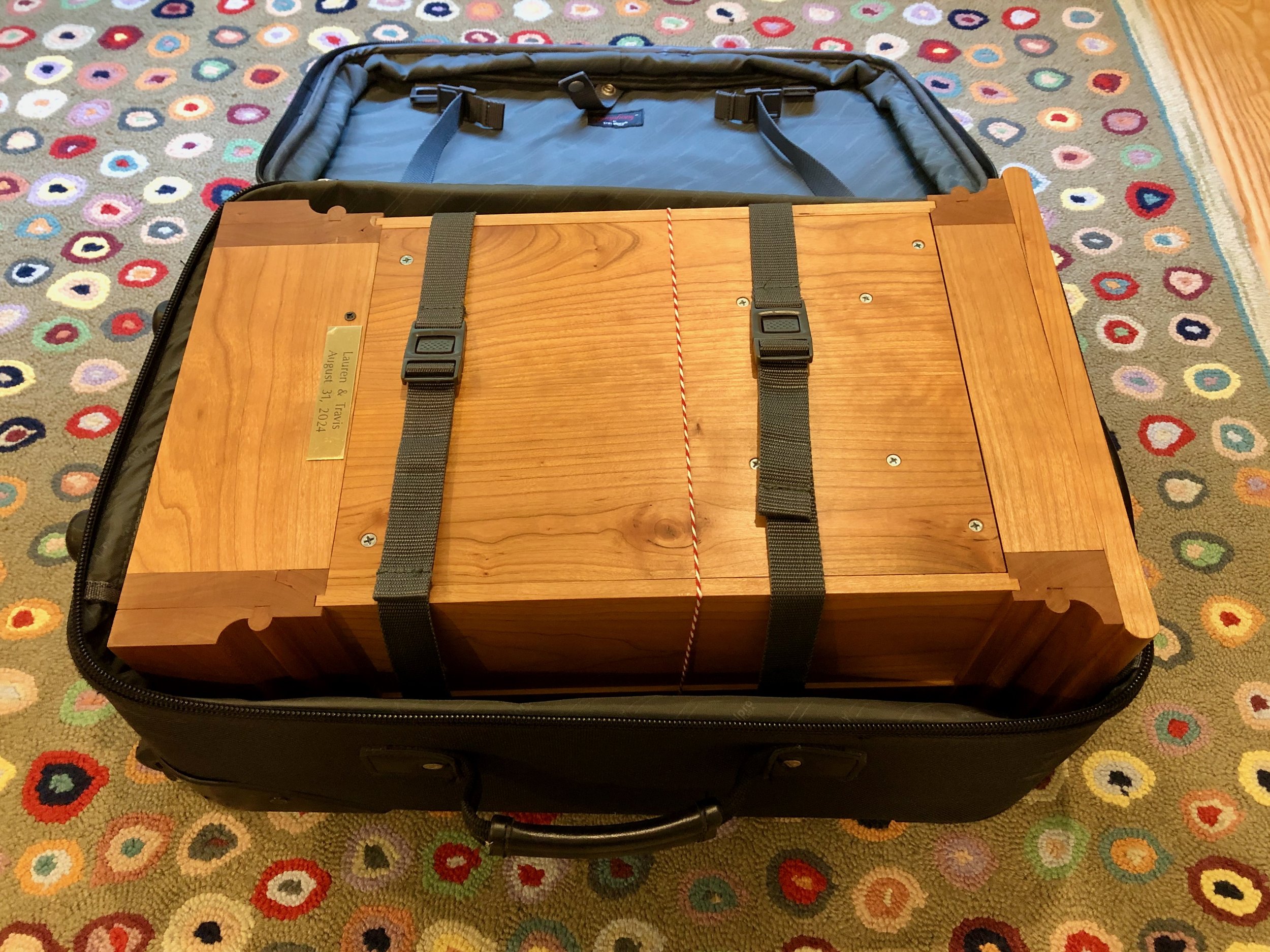
Note to self: the Square Rose defines the outer limits for wedding clock case dimensions.
Congratulations Lauren and Travis, and hats off to you, Chauncey Jerome. Time to enjoy a wedding!

Square Rose, ver. 2024