

Clock of the Westies

Clock of the Westies … get it? (all you Pop Rock fans of a certain age). Its meta-meta to be sure, being a pun on a famous spoonerism of the familiar saying “West of the Rockies”. It also describes my latest Project.
The occasion is the July wedding of my nephew Spencer to his lovely mate, Julia. They happen to reside west of the Continental Divide in Durango, CO which is where this “destination” wedding (for us) will occur, and my wife and I decided to gift them a clock to commemorate the event. Now, clocks are not traditional wedding gifts but they could become so in our family as Uncle Mark enjoys making them and he has no shortage of eligible nieces and nephews. Let’s see how this one goes.
Design
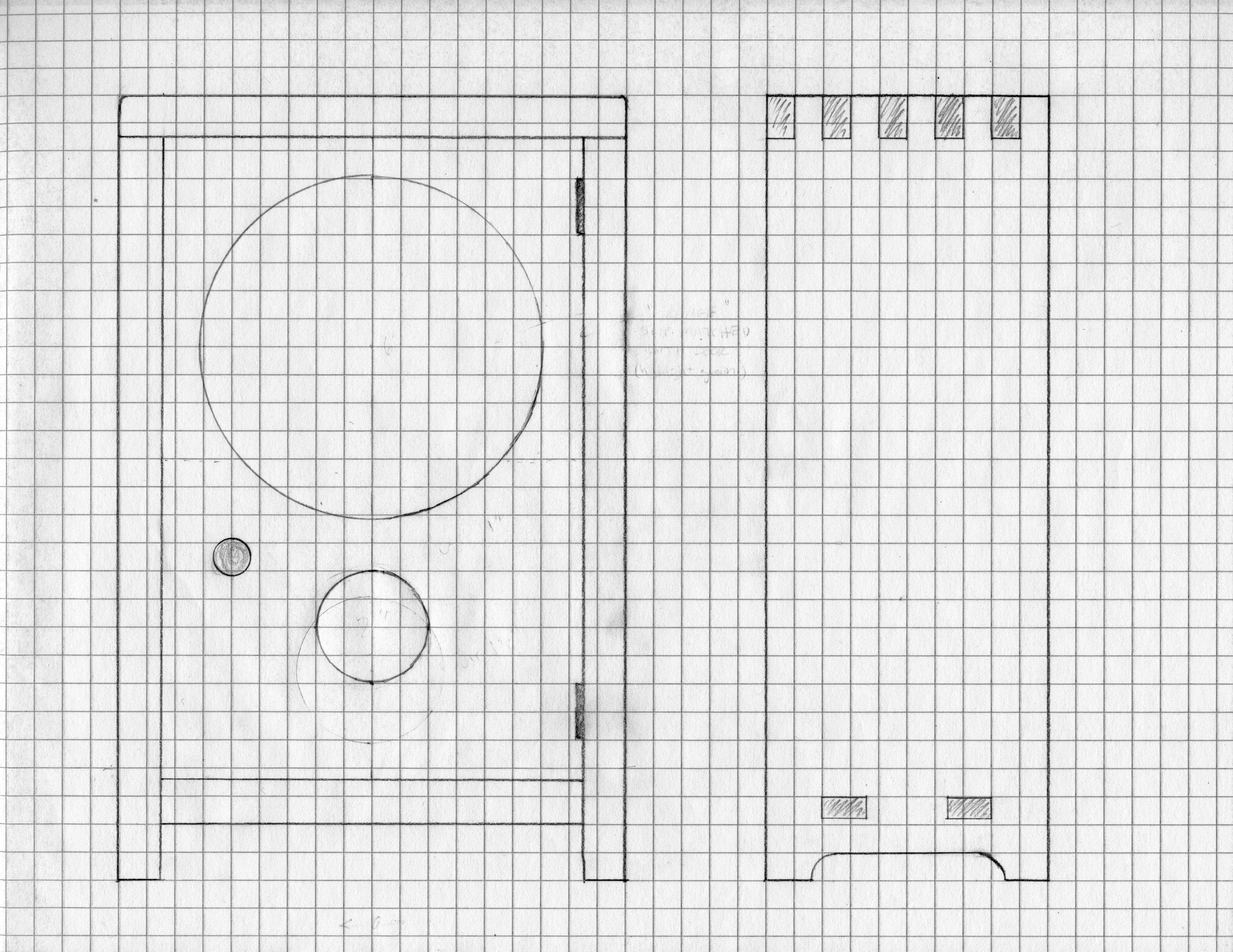
First, a bit about clocks. I like to explore Mission style clocks of the early twentieth century. I admire their “honest” appeal. Eschewing the intricate carving of German pieces, the stone and metalwork found in many French clocks, and the fancy moldings of early American designs, their essence is a simple profile and the seductive texture of wood. They also keep time, of course, but timekeeping was merely table stakes for marketing clocks during their heyday. The popular trends were set, and continually reset, by the case design. (Not unlike marketing automobiles on their chassis appeal.) For this Project I spent some time designing shelf clocks inspired by the Mission styles of the New Haven Clock Co. but decided in the end that these were still too made-up, too fancy. In my mind, a Rocky Mountain clock case needed to be plain-spoken and natural; in a word, “rugged”. But a rugged object that could still appeal to the eye. Going back to Arts & Crafts basics, I then conjured a modern version of the iconic Stickley mantel clock and found it to be both compelling and make-able. My guiding principle was: thou shalt not distract from the wood. A few changes were proposed in this case compared to Stickley’s design. Instead of a dodecagonal face with numerals, this one would be round and numberless (think Movado museum watch). I could also echo the round clock face opening with a circular pendulum reveal, common in other Craftsman and Shaker cases. A rough plan was drawn on graph paper but I was prepared to tweak all dimensions once the clock movement arrived and vital measurements could be made.

Materials
Butternut was the lumber chosen for this piece. This wood, Juglans cinerea, works easily and is remarkably soft considering its close relation to black walnut, Juglans nigra. With its dramatic grain and subtle orange-brown tones, butternut is the wooden equivalent of tanned leather. A single, 5 in. by 8 ft. plank of 4/4 stock should be all it takes to make the case. The clock face would be made of a less figured wood (TBD).

Butternut clock stock
The rest of the materials are all metallic and mostly brass: the clock movement; pendulum; key; gong; grommets; hands and hinges. Everything but the hinges was procured from Clockworks, a terrific online clock parts store. Primarily serving the clock repair trade, they carry all manner of high quality horological goodies. Also, their informative website and live technical support are extremely helpful to the amateur clockmaker.
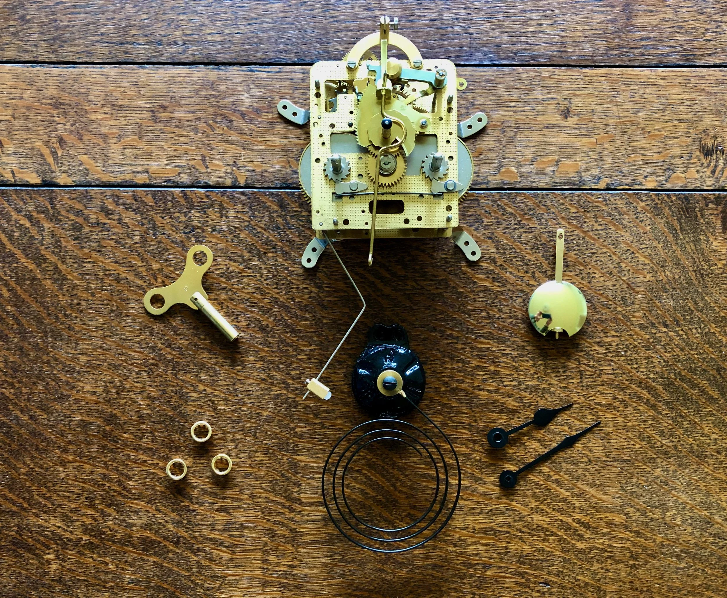
Clock components
Dimensioning
The clock case would be made from 3/4 in. boards, whereas the backboard, door and face would use thinner material. These thicknesses were created using the appropriate power tools and the mill marks then removed by hand before making the joint cuts. Like Stickley, I decided to use through tenons to fasten the bottom of the case, but opted for finger joints, rather than dovetails, for the top corners. Both finger and dovetail joints look beautiful when finished and, admittedly, both are overkill for this stress-free construct. However, finger joints would let me try something new and they also keep the shape repertoire for this elemental design down to two (circles, rectangles, trapezoids). But before I could cut the finger joints I needed a new jig.
Finger joint jigs come in several forms depending on whether you wish to create the joint using a router or table saw and, although commercially available, I prefer the homemade versions. Jigs for the table saw can be created by tinkering with a cross cut sled or by modifying the saw’s miter gauge. I opted for the table saw miter gauge version and, specifically, that jig described in a recent library book sale find, The Accurate Table Saw by Ian Kirby. Basically, this jig provides a mechanism to smoothly pass a vertically-oriented board through a spinning dado blade. The critical element is a 1/2 in. wide block of wood (aka key) that is affixed 1/2 in. to the right of the blade slot. The joint is cut by repeated passes through the 1/2 in. dado blade as the board is “marched” rightward in 1 inch steps. It works great, is easy to make from shop scraps, and you can get the whole concept from the picture below.
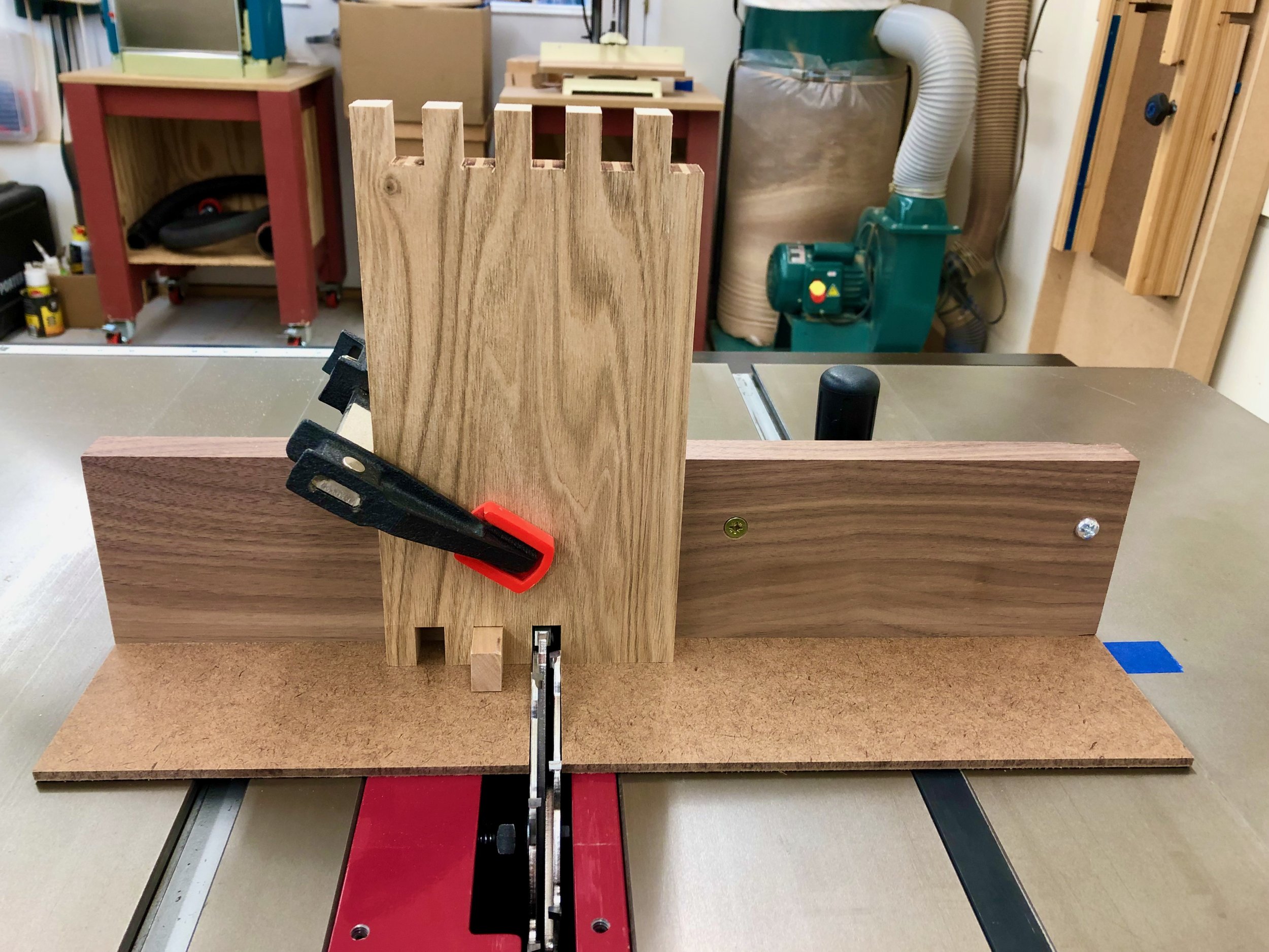
Shop-made finger joint jig in action
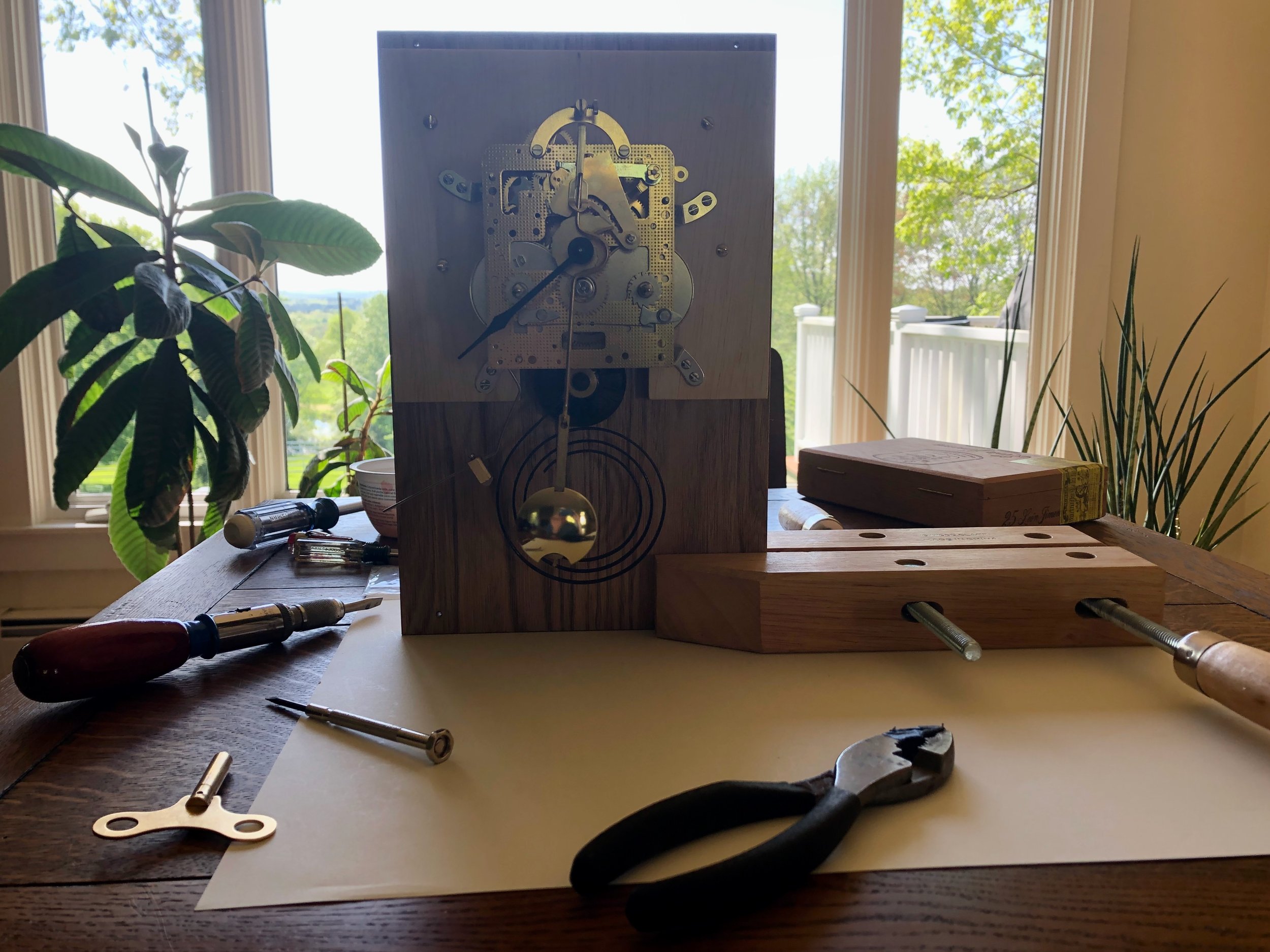
The fingers were fashioned on the top and side boards, and I also found that a simple modification of this jig could be used to accurately cut the tenons in the floor board. These were then dry-fit to describe the enclosure. Next, the clock mechanism was assembled on a stand and placed within the “case” so that the floor height and other critical dimensions could be fixed. The mortice sockets for the floor and rabbets to accommodate the backboard were now ready to be fashioned. Figuring out how to attach the movement to the case would await the next dry-fit.
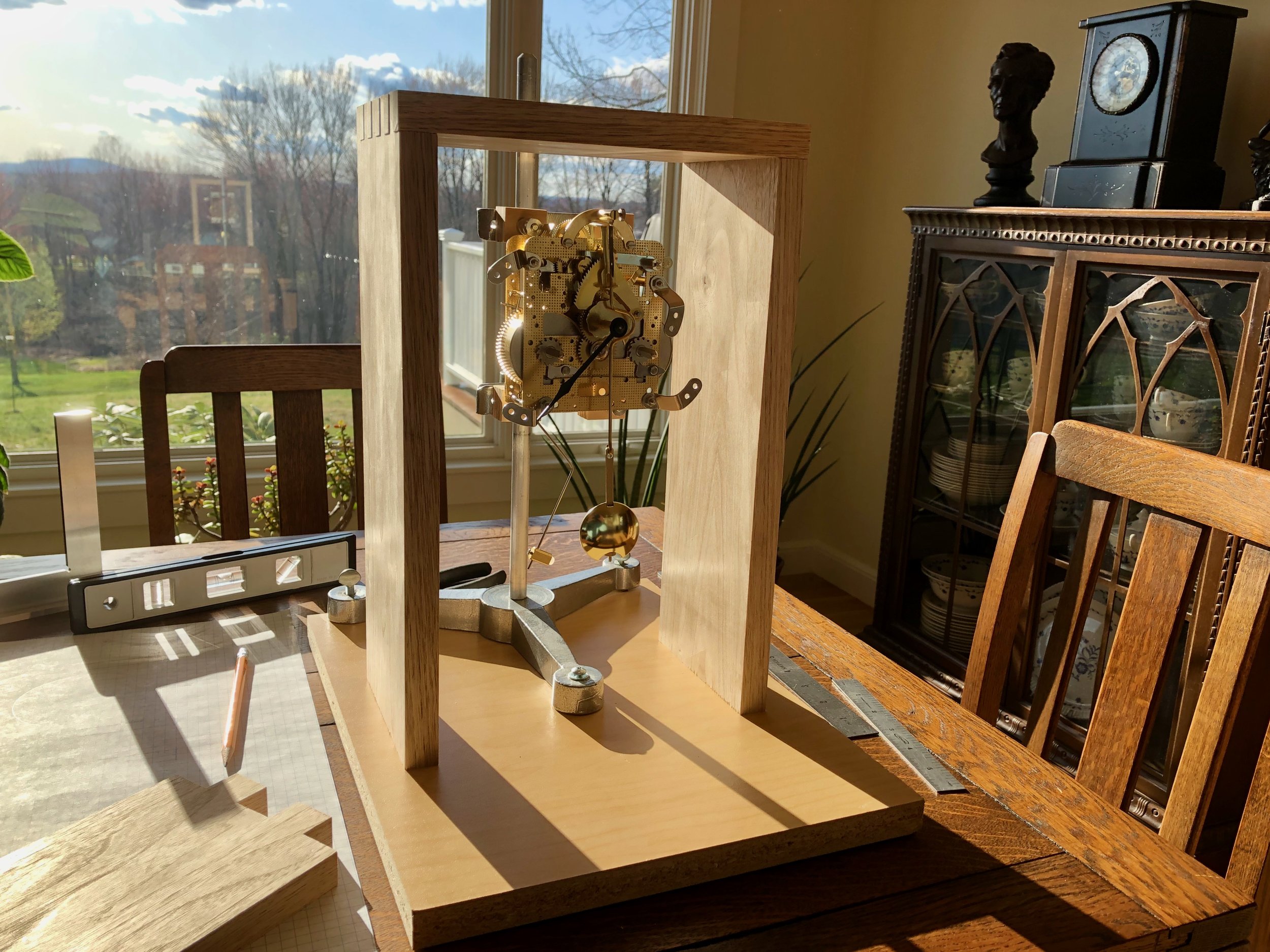
Clock movement mounted on a stand within the partial case assembly
Two mortices were cut (1/2 x 1 in.) on each side piece and then the tenons of the 3/4 in. thick floor piece were rabbeted to the correct 1/2 in. depth for a snug fit. Next the backboard was constructed by re-sawing a 4/4 butternut plank in two, thickness planing these pieces to 3/8 in., edge joining them together and then trimming this “new” board to the final width and length. A rabbet was then created along the back edge of the four case components to house the backboard. The design of this particular clock movement requires that it be mounted to the back of the case. The clock and backboard would then be secured to the case sides by screws to facilitate its removal for servicing of the mechanism over time. However, attaching the clock directly to the backboard would place the clock hands too “deep” within the cavity and so a square piece of 1/2 in. plywood was affixed to the inside to act as both a shim and a stiffener to prevent warp. A small cove cut into the bottom of the plywood allowed the gong to nestle into its proper place. The clock movement was screwed to the center of this board and then the entire construct attached to the dry-fit case using brass, pan-heads.
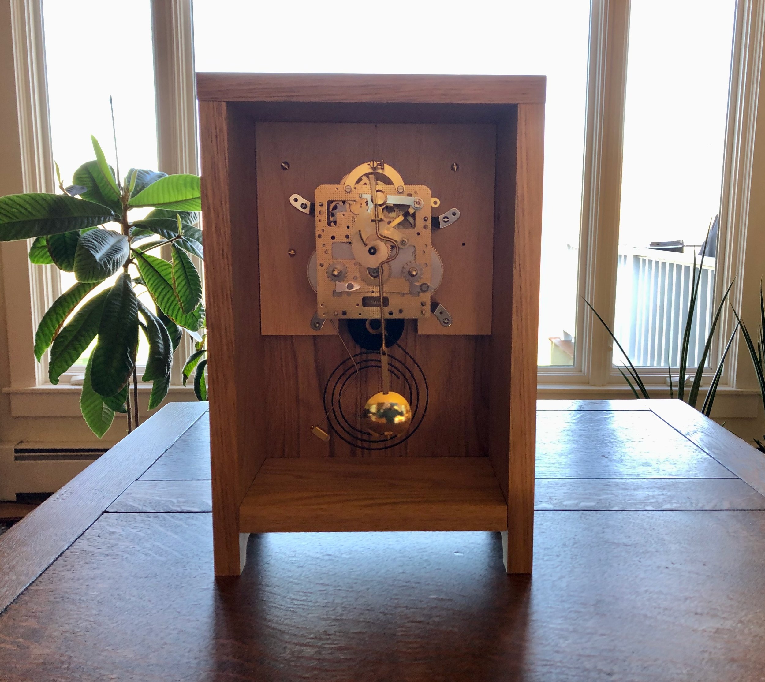
Movement and gong temporarily mounted in place
With the movement mounted in its final position the pendulum was attached and mock doors were cut from cardboard to help visualize how the different circular openings would work. In this design, a circular opening in the door creates the clock “dial” and, due to the chosen case width, this circle must be centered at a point 3 3/4 inches from the top and sides. Located 4 3/4 inches directly below this coordinate would be the center of the pendulum, and a smaller circular cut-out was proposed to serve as a window on its movement. The diameters of these circles were the design variables in play. The hands selected for this clock serve a 6 inch face, and a circular cut-out of this size would be the largest feasible opening in a 7 1/2 inch wide door. I liked the boldness of going to the max here. Below this, the pendulum bob could be nicely framed within a 2 inch opening and so a mock door with a cut-out of this dimension was tried first. Result: too large; too much underlying commotion. Next, to focus solely on the pendulum bob, a 1 inch diameter hole was tried. Result: too small; too distracting. I could have kept experimenting with other diameters but based on the first two results I was now concerned that any opening here would only detract from the beauty of the clock as an object. I then tried a mock door without any pendulum window. I liked how this version celebrated the proportions of dial opening to door mass and then I recalled the “thou shalt not distract …” motto. Decision: forgo the window; let wood do the work!
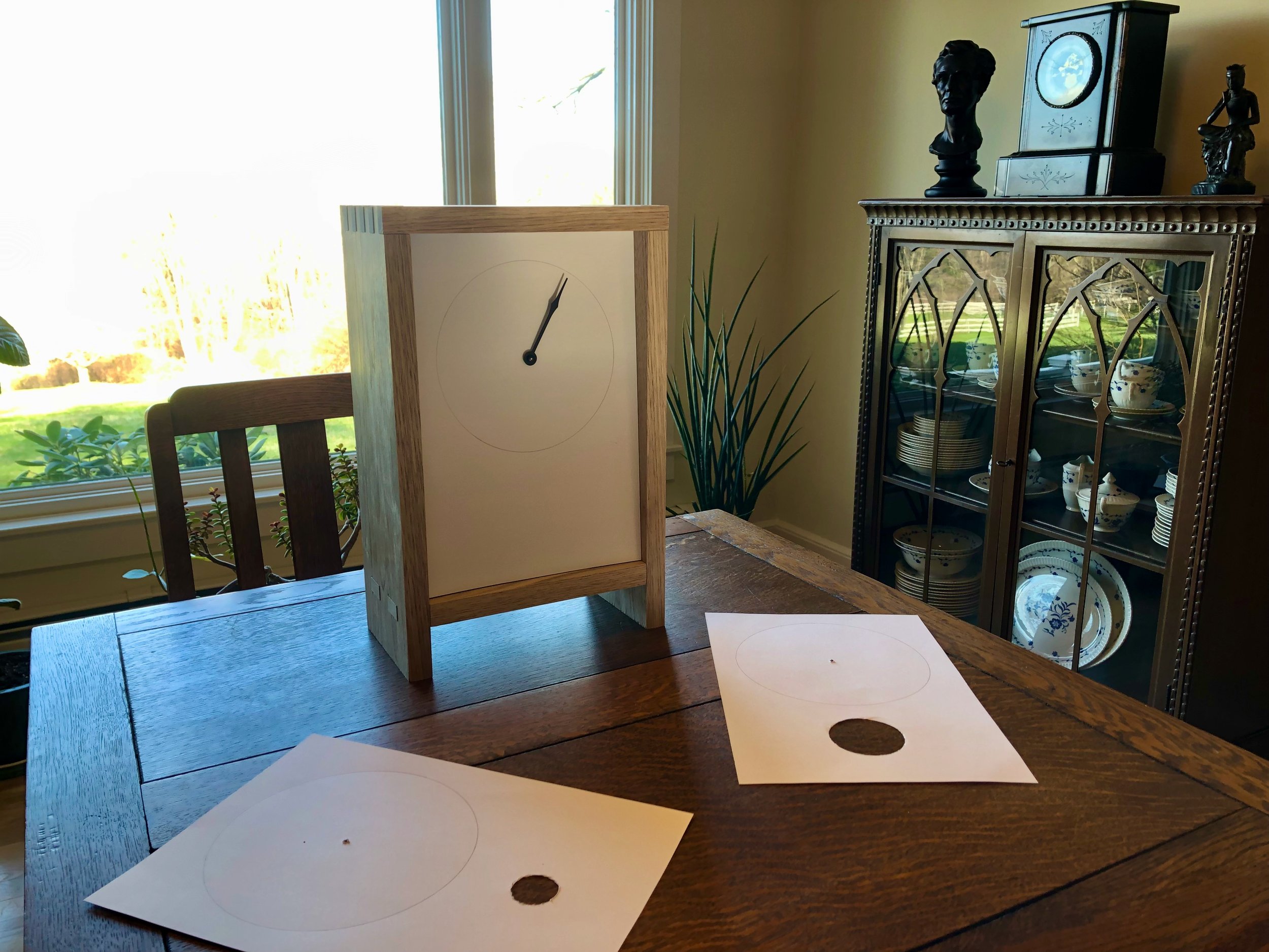
Mock clock doors
To make the door, the remaining butternut was re-swan at the band saw and subsequently thickness planed to a 5/8 in. depth. This was then chopped, jointed, ripped, glued and smoothed (all with great care) to create a slightly oversized door panel ready for the circle cut. A similar sized board was created from the leftover “end cuts” to serve as a test subject for this crucial procedure. To fashion the circle, I decided to use an adjustable circle cutting device at the drill press. This “cutter” consists of a bit that fits into the drill chuck and serves to register the center of the desired hole. Attached to this bit is an adjustable arm that holds a sharp piece of steel which spins along the desired circumference, thereby scribing a circle into the wood as the drill press is lowered. During the test run I found it was difficult to dig more than halfway into the board without the cutter continually seizing up. To remedy, I removed the board from the drill press, completed the central hole puncture with a hand drill, flipped the board over and re-mounted the circle cutter with precise alignment using this hole as the guide. The remainder of the cut on this “backside” proceeded as before and just as the knife began encountering difficulty it broke through. The result was a nice clean circular edge on both surfaces with a fuzzy “rind” of rudely severed fibers left in between. The rough parts were knocked down using sandpaper to create an acceptably circular hole. Cutting and sanding the “real” door in this manner proceeded without incident. Finally the sides of the door were shaved with a hand plane to achieve the desired fit within the frame.
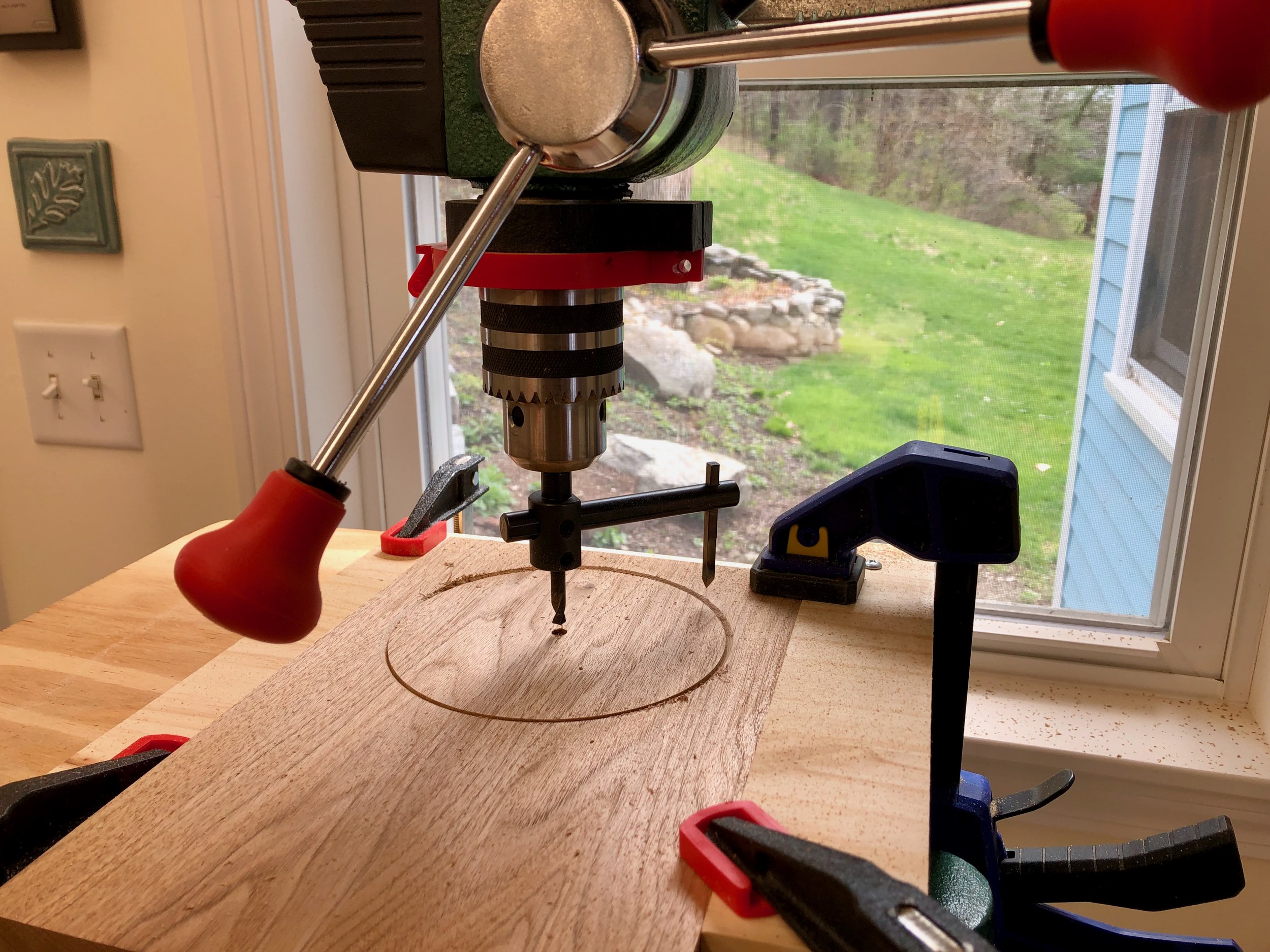
Cutting the “dial” on the drill press
To complete the case I needed only to: 1. shape the legs; 2. mount the clock face board; and 3. create mortices for the door hinges. The legs were easily fashioned from the side boards by drilling two 1 1/4 in. holes along the bottom edge at the drill press and then trimming the resulting “isthmus” at the band saw. For the clock face I wanted wood of a color that would both harmonize with the butternut case and also allow the black hands to be easily read at a distance. I chose some antique curly maple left over from the Stationery Chest Project for this. Its subtle character fits in nicely and could either be left bare & light or dyed some interesting shade, TBD. The chosen board was thickness planed to 5/16 in., smoothed and then cut to size. The tricky part is drilling holes for the hand shaft and winding arbors at the proper positions. Happily, upon request, Clockworks was able to provide the numerical spacings for these elements, as direct measurements on the movement are difficult. Once the holes were drilled I was able to rout a shallow trough on the backside of the face, above the hand shaft, to allow the movement’s front-mounted suspension spring and pendulum leader to swing freely. Four spacers were then prepared from butternut scraps that can be attached to the interior sides during assembly. These will support the clock face at the proper distance from the movement. Finally, mortices for the brass hinges were cut into the door and case side using a chisel. This is always a tricky job for me, but with patience it appears that I managed to cut out just the right amount of wood this time.
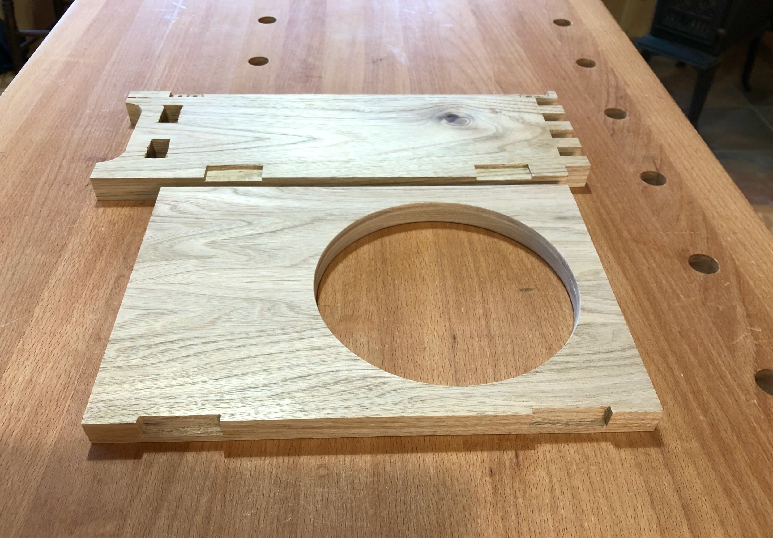
Door and case morticed to receive hinges
Assembly & Finish
After disassembling the dry-fit case and clock components (all the while making notes on the proper order for their re-assembly) it was finally time for glue-up. The mortice & tenon joints at the bottom were an ideal fit, but the finger joints up top were on the tight side and so glue was applied sparingly there for fear of swelling the wood prior to closure. Anyway, the case came together nice and square. Once the glue was dry the slight finger and tenon protuberances were all planed smooth and the case was sanded to 220 grit. Final sanding of the door and backboard were also conducted at this time. The plywood spacer board was then glued and screwed to the backboard and, with this piece tucked temporarily into the case, the four spacers for the clock face were attached to the case sides with glue. Dry-fitting the face board at this point revealed an unexpected challenge. The pendulum on this clock swings in front of the mechanism, and the hook at the end of the leader on which the pendulum mounts arches outward from the shaft just enough for this “highpoint” to rub along the interior of the newly mounted clock face. Routing out a slot, as for the suspension spring above, did not completely alleviate this friction source and so a 1/4 x 1 in. inch slit was cut out of the face to ensure the pendulum would swing freely. This slit is visible as a “feature” near the bottom of the dial, allowing a glimpse of the inner workings as the clock ticks away. Unplanned, but not unattractive.
On to the finishing steps. I liked the color of the butternut but would also be happy to see it darken over time. To assist the aging process, two applications of boiled linseed oil were applied (a 50/50 cut with mineral spirits, followed by a full strength coat) and after a couple days of curing, three coats of Arm-R-Seal wiping varnish were laid on over successive days. I used the satin sheen version of this product and find that it adds just enough life to the finish without tempting glare. The maple clock face, sanded to 400 grit, was finished with wiping varnish only. On test pieces I had played around with a couple dyes in the orange family. This color on the curly maple figure is stunning, but when placed behind the butternut door it made the clock appear disappointingly “artificial”. Good idea, but for some other Project.
A typical furniture piece would be complete right about now, but clocks are special; they need to both look good and also operate properly. The clock mechanism operates just fine as far as accurate gear movement is concerned, that was assured at the factory. Getting the gong right is the clockmaker’s job and involves two operations: aligning the hammer strike; and adjusting the minute hand. The hammer can only be aligned once all of the clock components are in their final position and so the movement was screwed to the backboard one final time and then held upright with a wood clamp while the pendulum and minute hand were affixed. To align the hammer, the thin steel rod supporting the head is bent/twisted, as required, to obtain a solid and squarely hit strike onto the outer ring of the metal gong. After aligning the strike I was able to adjust the length of the arm via a set screw on the head and then nip off the extra section of rod with wire cutters. A strong, stately gong every half-hour was the pay-off. Finally, the clock needed to be calibrated so that these gongs occurred whenever the minute hand was either straight up or straight down. This involves the iterative adjustment of a “square-holed” bushing nestled within the minute hand, itself, so that when pointed straight up it matches the rotational orientation of the square shaft when the gong hammer is released. A couple rounds of bushing twists followed by minute hand twirls and this clock was singing on the beat.
Adjusting the gong
The rest of the assembly proceeded as follows: mount the clock face with care to center the stem and arbors within their holes; press-in the brass grommets; attach the door hinges; mount the clock hands; and finally attach the pendulum. I chose to wait until this point to select and then mount the door knob. Torn between a wooden or a brass knob I collected a couple versions of each and then waited to get a feel for the finished clock, with the hopes that the choice would become obvious. Choice: brass. I liked how this material combined with that of the hinges and grommets to complete the exterior look and somehow suggest that there’s more brass to be found within. The knob’s mid-century design also kept things simple and round. A pleasing finishing touch.
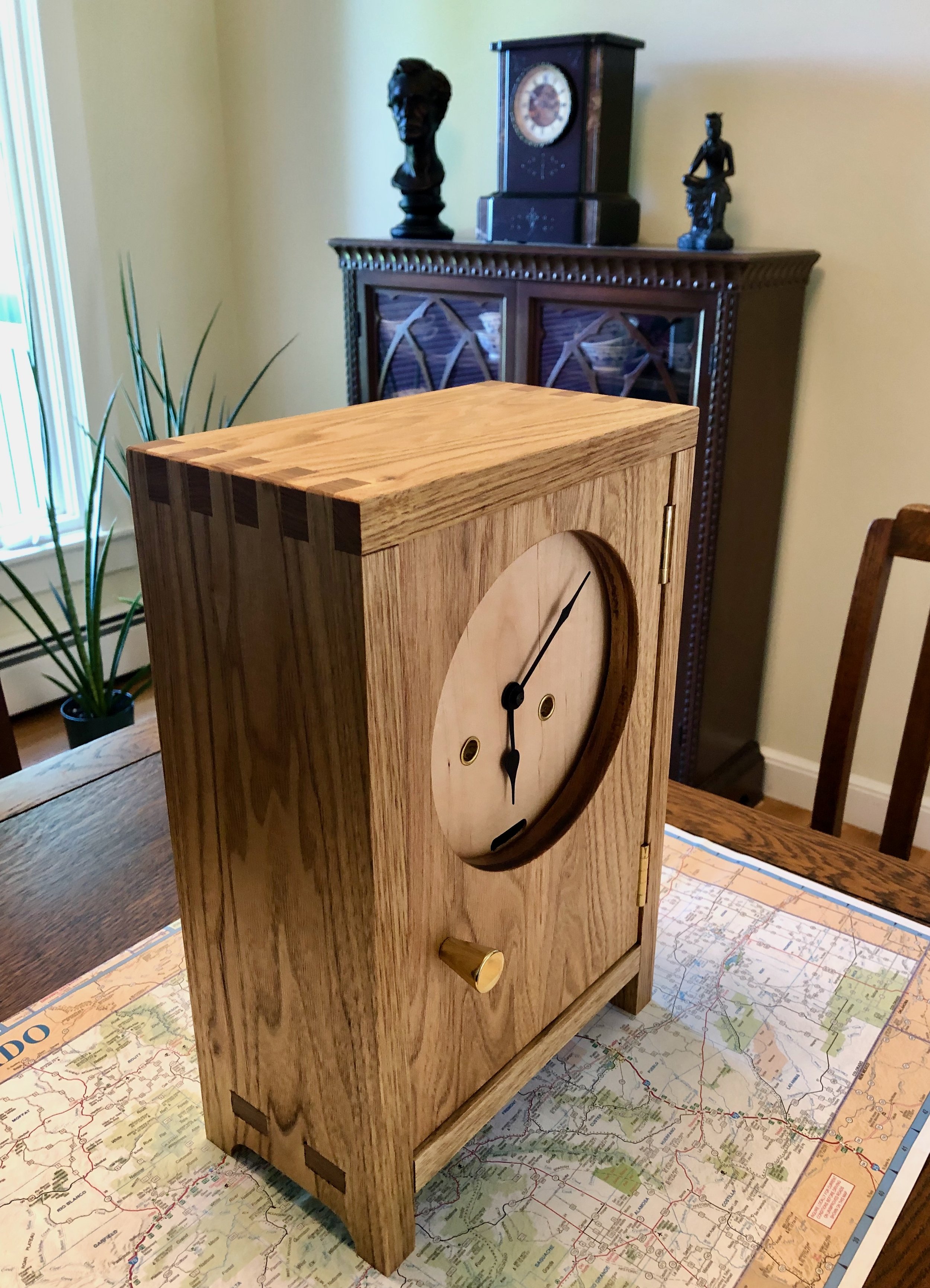
Clock of the Westies
Congratulations Julia and Spencer! Time to enjoy a wedding.