Under the Red Top
making the best of life & woodOne Year’s Growth
Well, we’ve just passed the One Year anniversary of redtopworkshop.com, the formal starting point for my furniture making endeavor. It has been a wondrous year for me and I thank you all for your support, critical comments, praise and patronage. What follows is a brief re-cap and a reflection on growth.
the Website
It seems establishing a website is the precondition for starting anything these days. And so as 2020, the year of my professional retirement, waned I found myself anxious to start anew and thinking a lot about website content and design. I researched a few platform options, discussed the matter with two knowledgeable sons and ultimately chose Square Space as my new entrée to the world. I have to say everything is made easy during set-up, and within a couple months post-launch my weekly fiddling with formats subsided and a comfortable routine for content creation was established. I soon realized that, rather than a transactional online marketplace, I merely needed a space to advertise my product and post a blog to generate/sustain interest. Even the “basic” Square Space package provides more than I require, but it is a nice product, and I plan to remain there.
I particularly value the blog element of the website. It’s fun to write, and I tell myself that customers also enjoy knowing the backstory of their new possession. My belief is that over time they will appreciate what the piece means to them, but they will start out with an understanding of how it came to be and what it has meant to its maker. That’s not nothing. Now, my use of the term “blog” is knowingly inaccurate, for most often the posts under this heading read like woodworking “articles”. That’s okay by me. I am seeking the folks who read blogs, even if they might release a “sigh” mid-way through the long ones. Only scientists and other professionals go online to read articles. Woodworking professionals might rightly consider these narratives to be naive or even self-evident. Nevertheless, I would hope they find them entertaining and I welcome their critical comments, but I’m hunting the larger herd. A writer needs to consider his or her audience and I imagine mine as ‘blog reader-types interested in furniture’ and, in particular, that subset who possess a few tools that they occasionally use to make things. You know who you are.
Anyway, after a couple of authentic, get-to-know-you blog posts I told the story of The Sumo Table from start to finish, and it felt right. Just as with most “first attempts”, re-reading that article today induces a cringe, but I value it for the door it has opened. Now, I wrote that one in retrospect once the furniture piece had been finished, but the next 12 Project stories (beginning with The New Sled) were told contemporaneous with the work. I believe this simple change in method has made me a better woodworker and has also enhanced the woodworking experience for me. I now spend some time each morning working on the latest blog, re-writing earlier passages and recounting what was about to occur in the workshop. Describing the work beforehand makes you focus on both the details and the sequence of operations. (It’s kind of like formulating a new hypothesis and then planning the proper laboratory experiment.) Reworking this text the following morning helps me to learn. Reflecting on what went well and what went awry, comparing these facts with the first written draft, and then correcting the story accordingly, promotes the recognition and retention of lessons. It also adds vitality to the work experience.
the Projects
Making the transition from hobbyist to full time woodworker really shortens the lifespan of a Project. And having a full day to devote to one’s work also requires a new approach to time management. It’s all good. Happily, the Projects have emerged with a better-than-expected flow and variety. In 2021 I was able to complete 6 items for our own home & garden, in addition to a couple of extra fixtures for the workshop. I also finished 8 commissioned pieces for friends and family members. I don’t know how these metrics will compare to future output but it felt like a productive year. A fun year, too! My favorite was the Spirits Cabinet, but they are all special, of course. Nothing is more satisfying than delivering new furniture to a new owner for the new purpose that had so consumed my thoughts over the previous month. It warms the heart and goose pimples the skin.
Act IV, Scene 1
Upon reflection I can state that I have rarely learned more in a single year than I did in 2021. To be sure, comparable spurts were experienced during my first year of life (1961), that first year of graduate school (1983) and the beginning of fatherhood (1992), but that’s it. I hope it continues full bore until I become a craftsman. That is the ending I have in mind for Act IV. In addition to being considered a good person, scientist and father I would like to be considered a good craftsman. John Ruskin, the great 19th century thinker and founding member of the Arts & Crafts movement, asserted that a “craftsman” is more than an amateur and, just as important, less than a virtuoso. Ruskin’s controversial stance was that “craftsmanship” - the work produced from this middle ground - was both needed and valued by a public unable to appreciate outputs from the extrema. I agree. A well-intentioned amateur still lacks the ability to truly satisfy, and the fully capable virtuoso is consumed by details of perfection beyond the masses’ desire. A craftsman satisfies desires. That’s what I am trying to do.
Simply Done
Here’s a good one. My wife and I recently shared a lovely dinner at the home of close family friends, both authors. Like the meal, the conversation on these occasions is always stimulating, generally hitting every compass bearing before landing, inevitably, on some aspect of furniture. Uncanny! I should disclose here that the interior of this home is like a comfortable gallery, replete with fine Japanese furnishings, original artwork (created by the hostess) and delightful antique wares. Special! And yet a request was made for a couple of new furniture pieces: end tables that could fit alongside modern chairs to help create a book-lover’s niche within the larger space. Now, there’s a lot to be solved in that statement but such is the power of furniture. As the evening progressed we talked enough about wood, dimensions and functionality for me to get an idea of the priority of requirements before saying our goodbyes. Next morning, once the wine had worn off and both parties had time to think more about the possibilities, the collaborative power of email was employed to finalize a commissioned design after only a few rounds of back-and-forth. Fun!
Design
The customers were looking for something both bold and simple. Easy(?). While their remodeled mid-century home retains many original details, the dimensions have changed and I was afraid that a mid-century modern furniture design would appear too dainty in this enlarged setting. Some related forms, Brutalist, Bauhaus, Danish were explored but these seemed either too curvy, too leggy, or both. Asian items would work for this purpose in other homes but they could never compete here. In the end, we decided on a minimalist design related to an example found online. I consider it a good thing to struggle during the design phase. Pondering different possibilities, their modifications and hybridizations, helps to express what is needed from all that is possible. I often jot down interesting, discarded ideas in the hopes I will stumble upon them to satisfy a future Project design. What? it could happen!
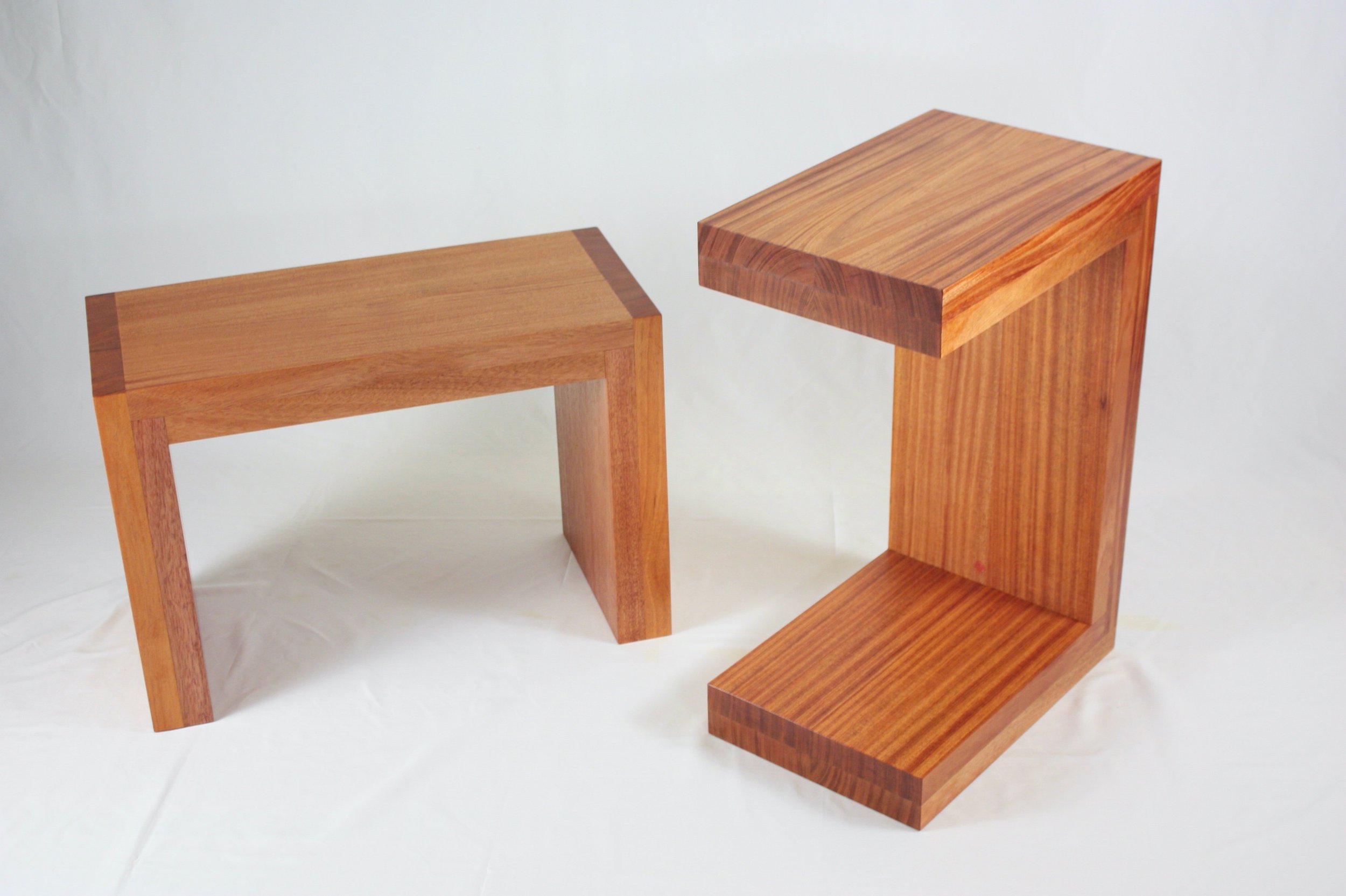
These tables will be large, chunky and symmetrical. Sculptural but not sculpted. No hardware, all wood. The design supports two posture options, upright or reclined, and I can imagine either working to satisfy the original request. And, as always, both the wood species and the board specimens are important components of design. Defect-free material with well-behaved grain would be important for imparting dignity and, after consulting my sons who think a lot about this stuff, it was decided that a richly colored wood was best. Other “looks” are possible but, at last, I was visualizing these tables as pieces that could hold their own in the museum.
Style = Simple
Materials
Size rules! The thickness of the table is 3 inches - everywhere - and to achieve this mass with readily available materials I needed to either look for extra hefty 12/4 dimensioned planks (12 quarters of an inch = 3 inches) or use two layers of the more commonly available 6/4 material. I opted for the latter. Even then, it would be a trick to take this “rough wood” dimension and maintain a thickness approximating 1 1/2 inch after dressing both sides even and smooth. By the time a rough 6/4 board is fully surfaced at a lumberyard (so-called S3S) it has usually been reduced to 1 1/4 in. thick. The choices were then: use this to make tables thinner than desired; purchase 8/4 stock and create a LOT of sawdust on the way to the desired thickness; or get creative. As to wood choice, I had my eye on African mahogany, given its uniform yet fascinating grain patterns and the potential to achieve a deeply colored finish. Although not genuine mahogany (Sweitenia macrophylla), this wood (Khaya ivorensis) is the most common of the “mahogany type” woods and has been imported to North America in large quantities for over a century. Today, this wood comes from countries on the West African coast (Ghana, Cameroon, Congo, Gabon, Ivory Coast and the Central African Republic). It is lighter in color and a bit more fussy to shape & smooth than genuine mahogany, but clearly the more sustainable and cost effective choice, making it worthwhile to learn the tricks of woodworking this material. Surprisingly, and perhaps because of its foreign source, the rough “6/4” African mahogany was a full 41 mm (almost 1 5/8 in.) thick. This should make surfacing to a final dimension approximating 1 1/2 in. a snap. Sold!
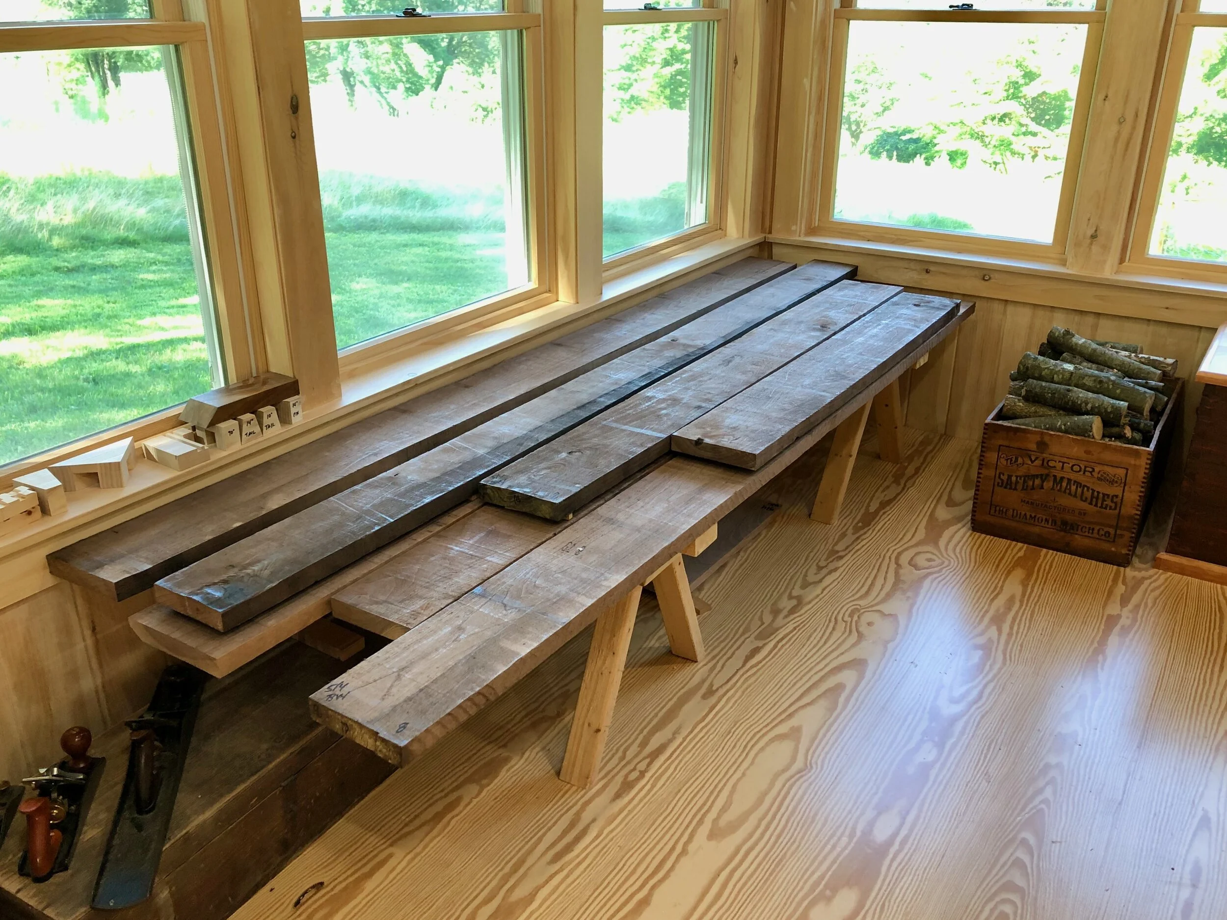
Bonus-sized 6/4 African mahogany, rough and ready to go!
Dimensioning
Not a lot of manipulations would be needed to prepare this Project for assembly. Once the lengths of all 24 parts were marked in crayon along the board surfaces these could be cross cut to size, planed to a uniform 1 1/2 in. depth, jointed square on one edge and then ripped to a final 6 in. width at the table saw. That was the plan, anyway. In the event, the brawny, 8 ft. long boards turned out to be rather unwieldy to work with at the table saw. Their thick bodies consumed the entire saw blade exposed above my cross cut sled causing burn and some kickback as each cut was completed. Not good - not safe. What I needed was a new saw. (Yes!)
As it turns out, I had been contemplating an upgrade of my 10 inch Makita miter saw to the larger, more advanced model for some time. Don’t get me wrong, I liked my old saw, a founding member of the Workshop, but the new model has some irresistible advantages. In addition to chopping, this 12 inch version also has the capacity to slide across the cutting bed allowing one to accurately cross cut boards as wide as 14 inches. In design it resembles an inverted radial arm saw, that 20th century workhorse now relegated to lumber yards and the basements of diehard enthusiasts due to its inferior safety record. Unlike the radial arm design, the blade of the sliding miter saw cuts as you push it away from you, and only reveals the spinning blade as the cut is occurring. Smart! And, of course, all of the tilting miter features are robustly engineered into this saw, too - it’s a Makita.
Well, I purchased the new saw, mounted it onto a newly constructed bench and it worked great to complete the rough cutting of “6/4” mahogany. The resulting 24 boards (plus a few extras) were then planed smooth on both sides to achieve a uniform thickness of just under 1 1/2 inches. Proper technique would be to “flatten” one side of a board on a jointer before using the thickness planer to make the opposing side parallel and of desired depth, however, the bed on my 6 inch jointer is too narrow to handle this stock and so I used the planer on both sides. The African mahogany boards selected had been quarter sawn at the mill and since this grain orientation resists warp I had the good fortune of starting with remarkably true stock. I think it’ll be okay.
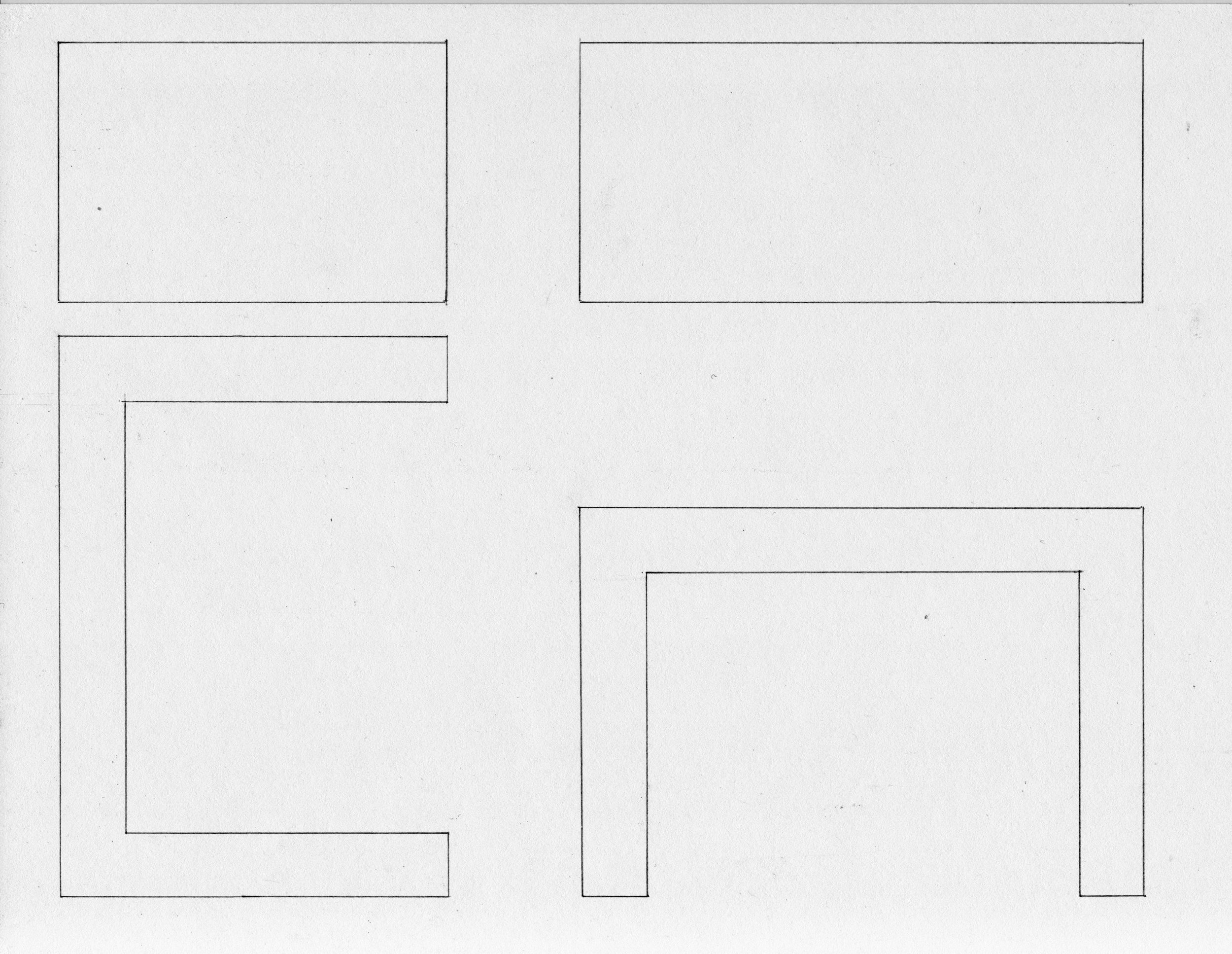
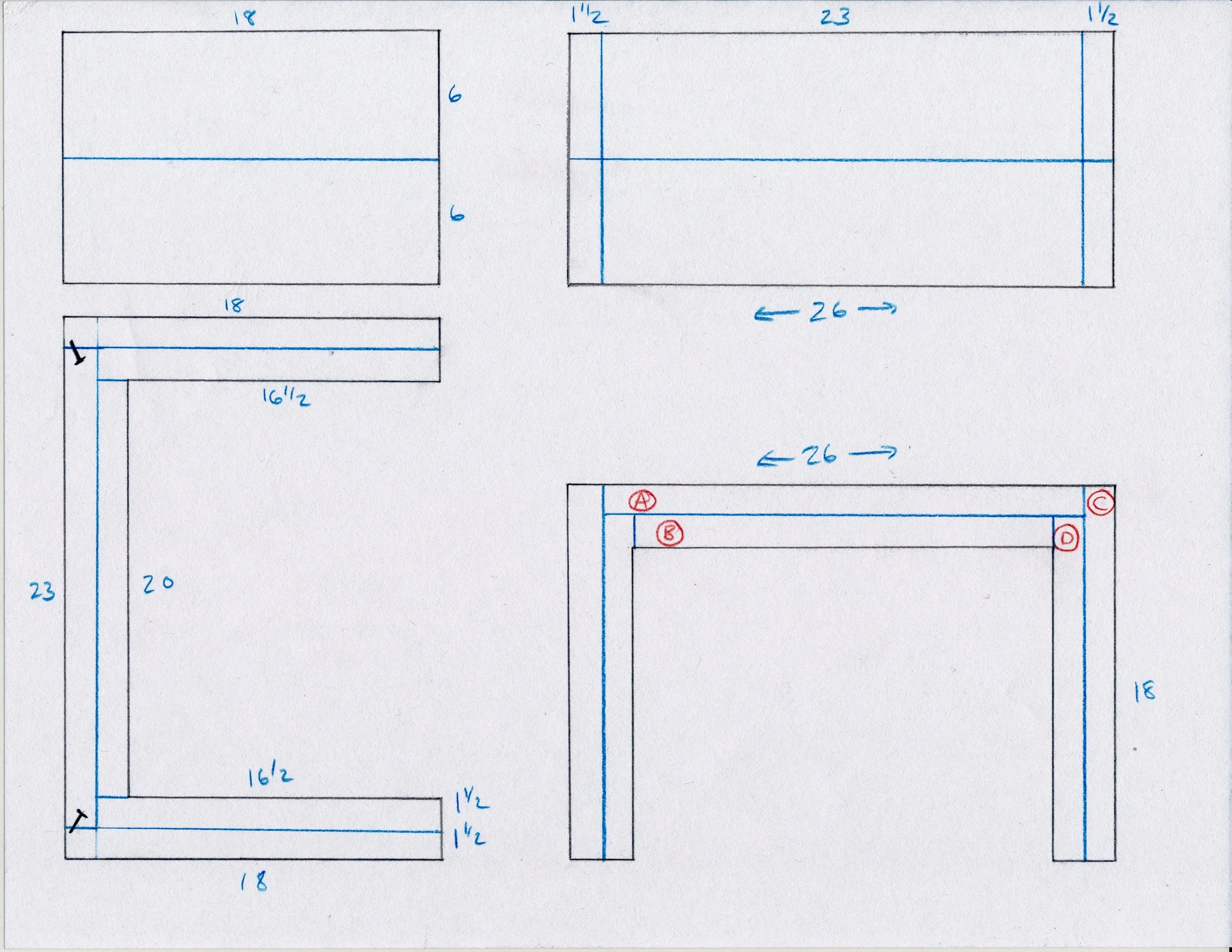
The pattern for this design uses twelve boards per table and the various sized components were marked: A-D. Each piece would be comprised of 2 A’s, 2 B’s, 4 C’s and 4 D’s. Since the lettered parts would be glued side-by side, much consideration was given to match the color and grain patterns for each pair. Anticipating that one table might be used in the upright position and one reclined I also chose what I considered to be appropriate grain patterns for each orientation. Black and red colored Sharpies were used to distinguish between the siblings. Once all assignments had been made, the “best” edge of each board was jointed square and the opposite edge sliced-off at the table saw to a width of 6 1/32 inch. The “extra” 1/32 in. was then trimmed during a single pass through the jointer to give glue-up ready surfaces on 6 in. wide boards. The penultimate dimensioning step was to cross cut the boards to a uniform size = [final length + 1/2 inch] at the sliding miter saw.
It was at this point that I needed to decide how the corner joints would be formed, as the joint type would dictate the order of board assembly. Several alternatives were considered, the main objective being to augment a less-than-ideal “end grain” glueing interface. Even using modern adhesives, fastening boards by glueing to the end grain of wood, a so-called butt joint, produces a weaker than desired bond. This structural weakness is the reason that all of the couple dozen more sophisticated joint types exist. Through one mechanism or another these joints go beyond a sole reliance on end grain glueing. Sparing all of the considerations for/against the unselected options, I decided, in the end, to go with butt joints augmented with mechanical fasteners (screws). It just felt like this piece was too heavy to rely solely on the glued fibers of dead wood, no matter how mingled the joint. But fret not, the screws would be positioned to leave no trace of their existence in the finished piece. Much like the sinew surrounding the joints in our own frame, their cohesive presence beneath the surface will ensure structural integrity. Clever!
Anatomical plan
Assembly & Finish
Plan in hand, the first step was to edge join the paired 6 inch wide boards to create 12 inchers. 2-3 Biscuits were used within each joint to ensure alignment and strength. It is difficult during this glueing & clamping procedure to exactly align the ends of the boards and so they were assembled as even as possible and then re-trimmed at the sliding miter saw to get a perfectly straight and square 12 inch edge. That’s where the “extra” 1/2 inch mentioned above comes into play. Following this, eight pocket screw holes were drilled into the underside of each “AA” piece in preparation for assembly. The surfaces were then smoothed using a combination of hand planes, card scrapers and sand paper and dry-fit to ensure mutual compatibility.
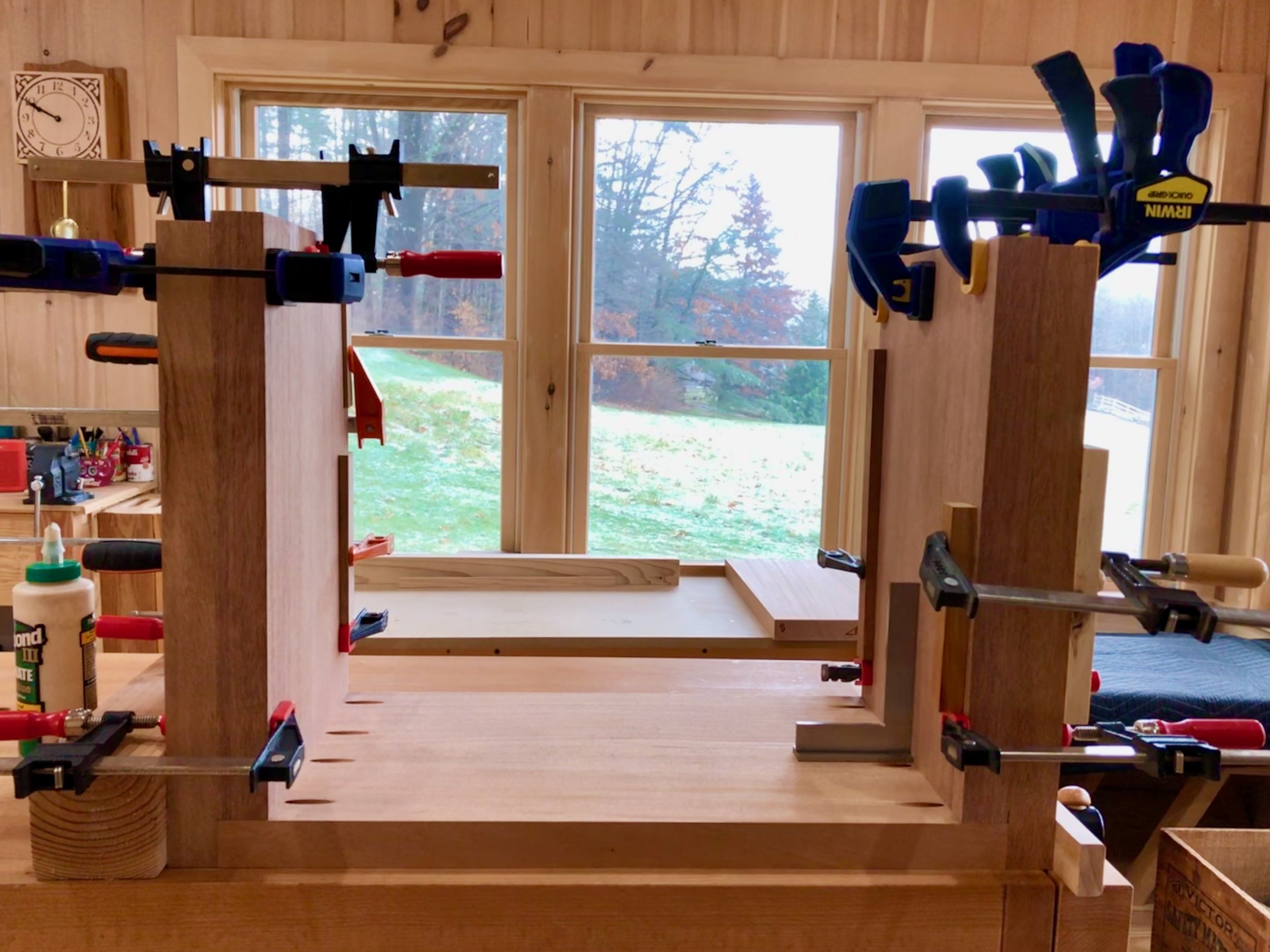
To assemble, part AA was secured to the two outer leg boards (CC’s) by the use of four pocket screws on each end. This constitutes the only linkage of perpendicular parts. The remaining boards (2 DD’s, 1 BB) were simply laminated, using glue, to the underside surfaces to both provide the desired mass and impart sag resistance along the major beam. Pretty basic, although I was surprised by the challenge of getting all of the boards properly aligned before clamping. Once dried, most of the newly formed “imperfections” could be worked straight and square again by planing/scraping the edges. All remaining features attesting to a handmade origin are (ahem) provided free of charge. Splendid!
Laminating legs onto the pocket screwed frame
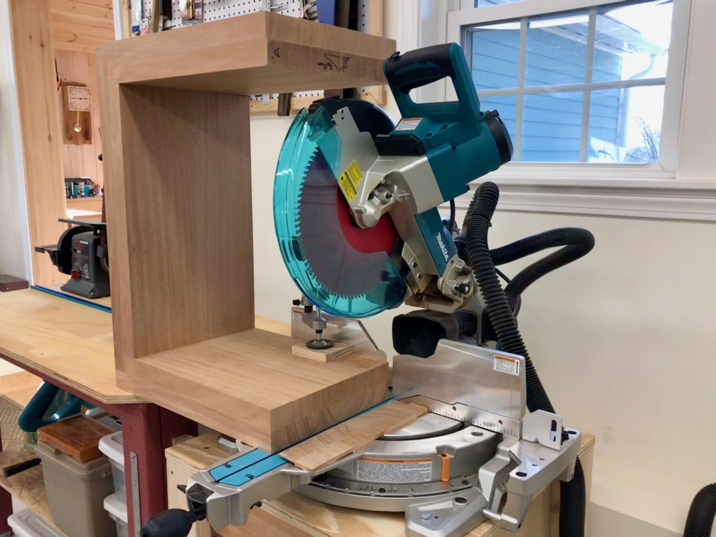
The final saw cut was to trim the bottoms of the “legs” at 18 inches in length. Here’s where the sliding miter saw earned its keep as the only tool in the shop capable of handling the task.
Making the “money cut”
From here it was just a matter of smoothing all surfaces with sandpaper and then sealing the wood with finishing products. Following an exploration of various dyes and glazes to deepen the wood’s color it was decided to just leave things alone and let the action of sunlight exert its aging influence over time. After all, the function of most wood stains is to instantaneously achieve the “look” of naturally aged wood. They do this well, but often at the expense of clouding the grain and unnecessarily splotching things up. Stains have their place but not on this Project. However, even when foregoing stains there remain a vast array of finishing options depending on what you wish to accomplish. The objectives here were: 1. accentuate the grain; and 2. impart durability to surfaces that would be used as both table and seat. After a bit of playing around I chose linseed oil to achieve the first goal, and a high grade polyurethane varnish to assure the second. The oil was thinned considerably to reduce viscosity and promote absorption - two applications seemed to do the job. This was followed by three coats of varnish and a final buff.
Refined & Simple
In their final setting they make a handsome pair.
It’s About Time
“A clock more than any other piece, needs to show fine workmanship, must be made from well seasoned wood, have perfect joints and be well finished.”
- G. Stickley (American furniture maker 1858-1942)
Well, thank you for that Gustav. Anything else? Actually, he is making a good point with that declaration. Here’s my take. The only reason for a clock case to exist is to be continually looked upon, if not examined in detail. Any clockworks fixed to a bare board would be perfectly functional if referencing time was the only goal. But there’s a higher calling for clocks to be pleasure givers, and this purpose demands fine workmanship. Choosing a clock, whether as a mantle accessory or a hallway showpiece, has always been a significant decision relying largely on the quality of the case. Especially in the pre-electronics age, when everybody owned a mechanically-driven clock, clockmakers competed on the appeal and durability of the case. The variety of clocks produced in every corner of the world during the 19th and early 20th centuries is impressive! and I urge you to check it out. Clocks, and timekeeping in general, have a rich history that is fun to research, but I will save that topic for another day (exhale now).
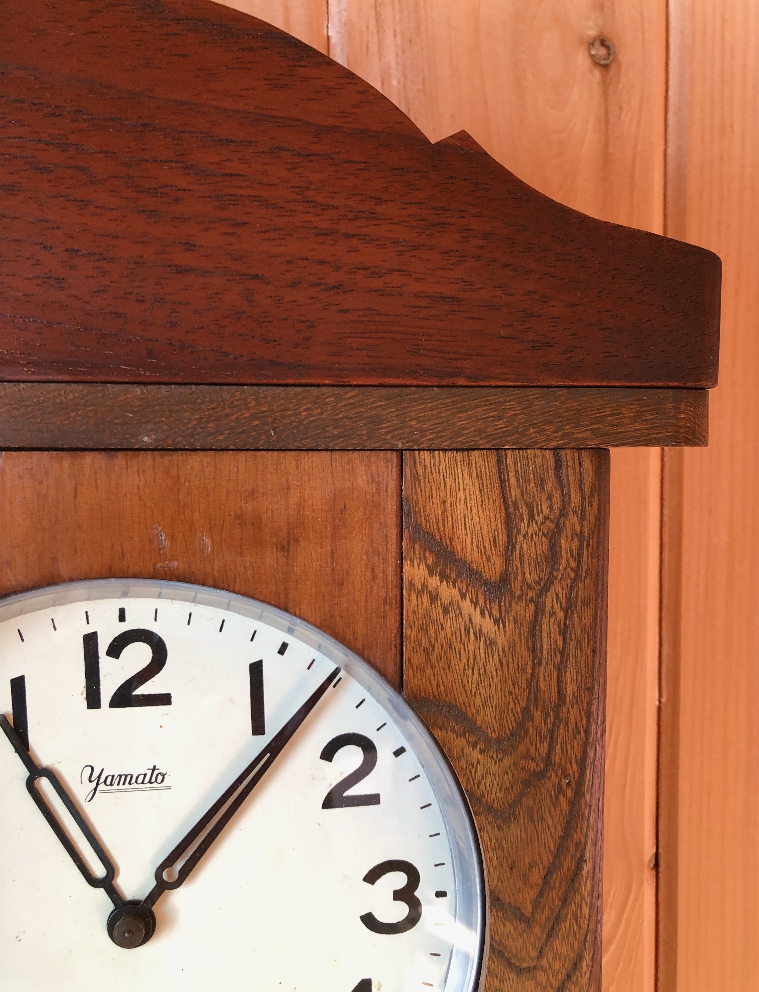
I mention all of this because my current Project is a clock. Specifically, a clock case - that miniature furniture piece surrounding the time and gong mechanisms that gives a clock its personality. I first gave clockmaking a try down in the basement workshop, making a wedding gift for Ben and Allison. For inspiration, I found online images of some mission-style clocks produced by the New Haven Clock Co. (c. 1904) and was intrigued by their look and potential make-ability. I went on to design a shelf clock of similar proportions to their Los Santos model, ordered some mechanical parts, still being manufactured for classic clock repairs, and put the whole thing together out of quarter sawn white oak. It is definitely a “first attempt” piece but still heirloom-worthy. What’s more, I found it was a real joy to make clocks and vowed to improve my craft by building others. That was almost 3 years ago … Time actually does fly!
Design
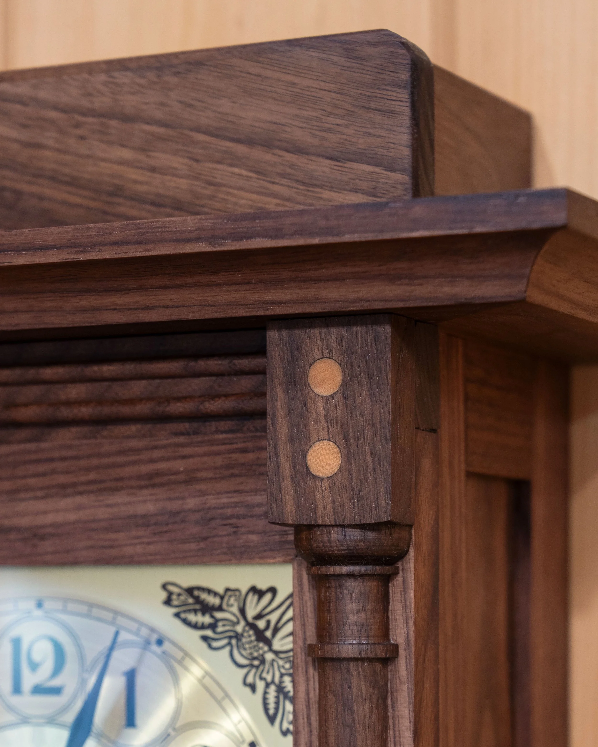
This Project is a wall clock for my workshop based on a Craftsman design. The design comes from a published compilation of furniture plans by Gustav Stickley and originally appeared in the December 1905 issue of The Craftsman magazine. I would intend to closely follow the published plan with just a few changes to proportions and methods.
Basic wall clock plan (1905)
G. Stickley Making Authentic Craftsman Furniture: Instructions and Plans for 62 Projects Dover, 2018, p. 49.
Materials
I wanted a workshop clock with the potential to inspire whenever I looked up from my bench and so for materials I selected some wood with particular meaning for me. For the box sides and back I would use re-claimed, pecky cypress boards that had been discarded during a renovation of our former New Jersey lake house. This stone cottage, built in the early 1940’s, was completely paneled in pecky cypress. The heavily varnished surface had darkened over the years but the warm, comfortable environment provided by these walls will always evoke special memories of that lakeside retreat, recently sold after delivering 22 wonderful years of family adventures. I had salvaged these boards during the move-out for use in just such a Project. The wood is mature bald cypress, intricately grained and deeply pocked by a brown rot courtesy of the fungus Stereum taxodi. It is a unique look, for sure. The wood was a popular mid-twentieth century paneling choice and probably has never been used in clockmaking, until now.
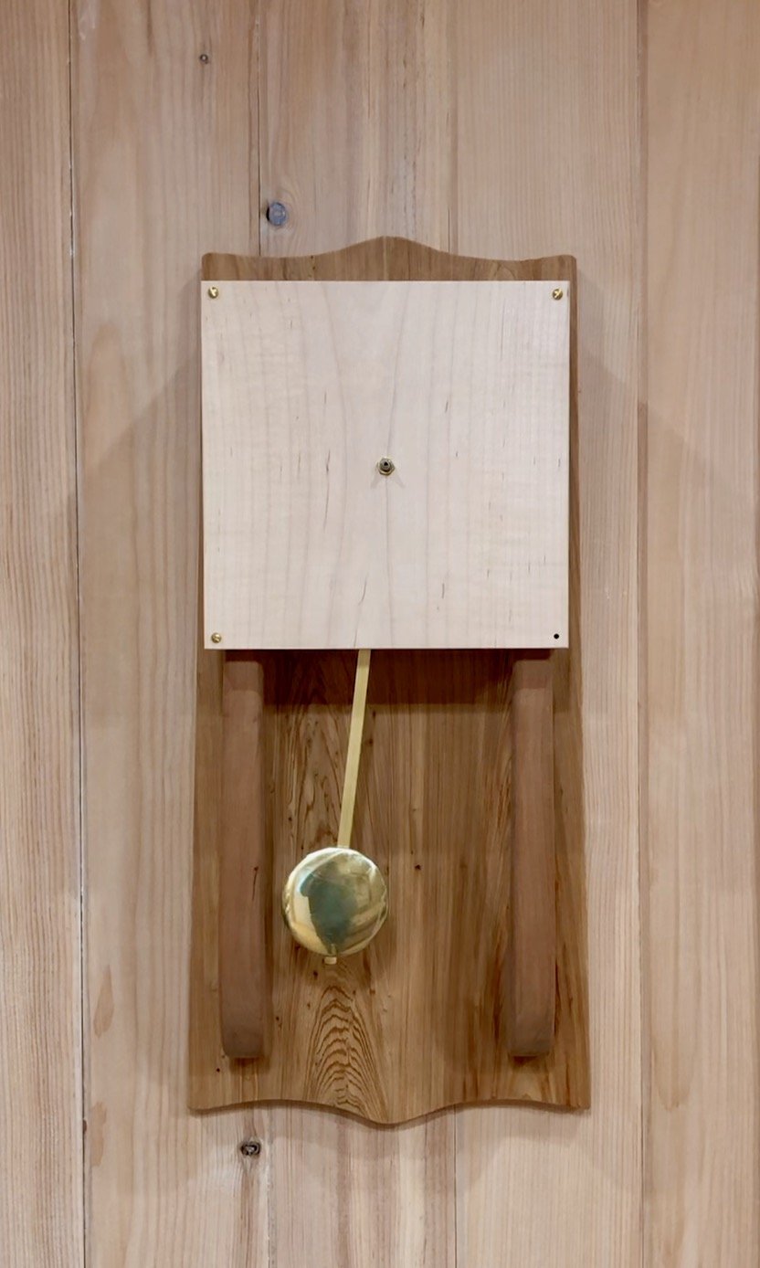
The clock face would be made from a piece of curly maple left over from the Stationery Chest Project and the two supporting bracket arms carved from antique redwood. Both of these boards originate from the family heirloom lumber described in earlier posts. The clock mechanism, pendulum and hands were procured from TimeSavers, one of the several remaining clock parts stores. While not my preferred option, I went with a battery powered quartz movement for the workshop to avoid problems down the road with sawdust in an oiled mechanical mechanism. Quartz clock movements, of course, do not require a pendulum, but for a few extra dollars one can purchase a version that will drive a pendulum to create the illusion of a mechanical clock. The final purchase, off Etsy, was a clock face stencil that will be used to paint the numbered dial. Using reclaimed wood and a quartz movement kept the out-of-pocket outlay reasonable, around $50.
Dimensioning
Things proceeded rapidly in this phase. First, one of the pecky cypress boards was thickness planed to 5/8 in., exposing both the raw grain and fungal cavities. This plank was then cross-cut in half. The backboard would be formed by mating these two boards and so care was taken to match the grain flow prior to biscuit-joining them together. Another such panel, used to make the four sides of the clock “box”, was planed down to 1/2 in., ripped to 3 1/2 in. in width and then cross cut into four, 9 inches long pieces. Rabbets at both ends of the two boards selected to become the “sides” were then cut with the dado blade on the table saw (1/2 in. wide by 1/4 in. deep). These would be joined with a “top” and “bottom” board of full thickness to make the square case, thus necessitating that these last boards be trimmed accordingly to ~ 8 1/2 inches. All of the boards were glued at this time and then finished smooth with hand planes.
Next, a rectangular opening (3 in. x 3/4 in.) was cut into the box bottom to allow the pendulum swing. This was accomplished by drilling “access” holes at the corners of the pencil-marked piece and then connecting these with a jigsaw cut. A chisel was used to clean-up the opening and square the corners.
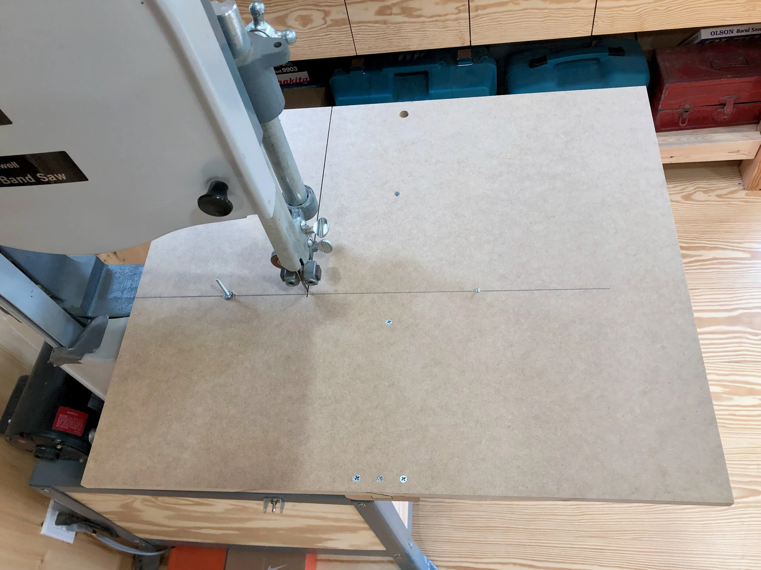
From here on things would become less square. It started with cutting both sides of the back to a taper using the track saw. The width was only reduced by 1 inch over the entire 24 in. length, but this slight deviation is intended to produce a refined, less “homemade” look. The top and bottom edges were then trimmed to a flowing pattern on the bandsaw. These cuts seem to go smoother for me with every attempt. A disciplined eye, trained to ensure that the penciled path, no matter how curvy, enters the cut in-line with the band saw blade is key. The curves were then smoothed-out with a sanding drum bit at the drill press. Finally, a chisel was used to create a V-shaped notch on the backside. This would catch a screw head allowing the clock to sit flat against the pine walls of the shop.
Next comes what Stickley refers to as the “brackets”: two curved arms that support the clock box. For these I chopped off a 24 in. section of an old redwood 2x4. The crusty wood was made square and true using the jointer/planer 1-2 punch. And while I could have kept planing off shavings to achieve the desired 1 1/8 in. final width, it was easier to trim the excess at the bandsaw. This was done in a manner to also remove some natural defects (splits and sapwood). A couple encore spins through the thickness planer and a chop at the midsection with the miter saw provided the roughly dimensioned stock. The pattern for the bracket’s shape was gleaned from the tiny magazine pic, sketched on graph paper, traced on to heavier card stock and then traced again on to all sides of the wood pieces. In the end, these brackets will just be affixed to the backboard and box so there is no “correct” measurement to be matched and fit. Still, it needs to have the right proportions in order to fit in. I had enlarged the plan by 33% to provide a workshop scale timepiece and so these brackets would be 11 in. long and a bit stouter than the original dimensions.
Bracket pattern marked onto redwood blocks
The marked boards were taped together and the “interior” curve was cut at the bandsaw. I thought I would shape the upper portion of the brackets before cutting the “exterior” curve to give me as much time as possible to work with square material. Using a combination of hand planes, wood files and sandpaper the top “spindles” were tapered and rounded to a first approximation of their final form. These pieces were then taped together again, with a shim wedged in between to fill the void from the recently created tapers, and the “exterior” curve was cut. Similar work on the base and exterior curves followed by a final sanding along all surfaces produced the bracket pieces. Dry redwood is an easy material to shape, making this first try a satisfying experience for me.
The last part to be fashioned was the clock face, itself. In his brief instructions Stickley calls for burning the numerated dial onto “box wood”. Ahh!, a rare glimpse into the pre-cardboard era. And while I happened to have a few old wooden boxes in the shop (trying their best to look busy as firewood bins) I decided to use a light colored maple board instead. I would also paint rather than burn the clock face with the help of a stencil pattern.
The maple board used was a discard from resawing a thicker plank during an earlier Project. To prepare this part I simply needed to thickness plane to a uniform 1/4 in. depth, sand smooth and cut it to a ~9 x 9 in. square. I sanded the oversized stock prior to dimensioning so that I would have matching, scrap materials to practice the oil finish and stenciling steps. And recalling Gustav’s maxim, I cut the face purposely larger than required, affixed it to the box with screws and then hand planed the edges flush to achieve a (near) “perfect joint”. The sharp edges of the clock face and backboard were then neatly rounded using sandpaper.
The final element of construction went beyond the 1905 plan and involved the care and upkeep of a quartz clock. Stickley’s plan called for a traditional, spring-driven movement which requires routine access to the clock face and pendulum catch, only. As such, the clock mechanism is generally secured within a dust-free chamber, only to be exposed every 5 years or so for oiling the pivots. In contrast, quartz clocks require regular battery changes, as well as a biannual adjustment for daylight savings time, and both of these operations require access to the rear of the clock. To provide ingress I could have cut-out a portion of the backboard, but this would mean regularly taking the whole clock off of the wall to perform maintenance. Instead I chose to make the clock box removable from the backboard and brackets. I toyed with hinging the clock face (or the entire box) along one of the edges but did not want the exposed hinge barrels to ruin an otherwise clean & symmetrical design, and so I chose to enable the entire box to lift off of the brackets. All that was required for this would be a reversible means for both attaching the box tight against the backboard and centering the face on top of brackets. For attachment, I used a magnet embedded within a small divot created in the box top that would rest upon a metal plate affixed to the backboard. To center, I drilled two holes in the bottom of the box, straddling the pendulum opening, that would snugly catch dowel pegs mounted to protrude 1/2 in. beyond the ends of the bracket arms. Trust me, it’ll work.
Once the parts were completed the whole thing could be dry fit, including the clock mechanism, to measure for the pendulum length and swing. Again, the pendulum is simply a beauty accessory on this clock so the only thing it needs to do is look pretty and avoid clanging into the brackets. The 2 3/4 in. round pendulum “bob” came with an oversized, 18 in. brass “rod” designed to be trimmed to the desired length at this point in construction. Once attached to the “dry fit” clock it was easy to pick a length that looked right, the question was would this length smack the bob into the redwood with every sway? Now, it is highly advised that a clockmaker purchase all of the timekeeping parts before embarking on case construction and I did just that. I also set the movement up on a stand that allowed the working pendulum to swing freely and attempted to take measurements of the moving arc along the rod. During these experiments, I managed to convince myself that all would be fine as long as I stuck to my measurements during construction. Nevertheless, there is a reason that people hold their breath whenever a new ship is launched. In the end, the rod was cut to 10 inches and I can report that the swinging pendulum floated free. (Hey! Somebody said there would be champagne?)
A postcard from the Shakedown Cruise
Assembly & Finish
All that was left was to disassemble the parts, apply the finish and clock face and then reassemble. It was the grain of all three woods that I wanted to show off and so I went with the General Finishes “Seal” products - one coat of Seal-A-Cell, followed by two of the Arm-R-Seal satin finish. These oil finishes served to nicely highlight the varying wood colors and impart a pleasing “glow”.
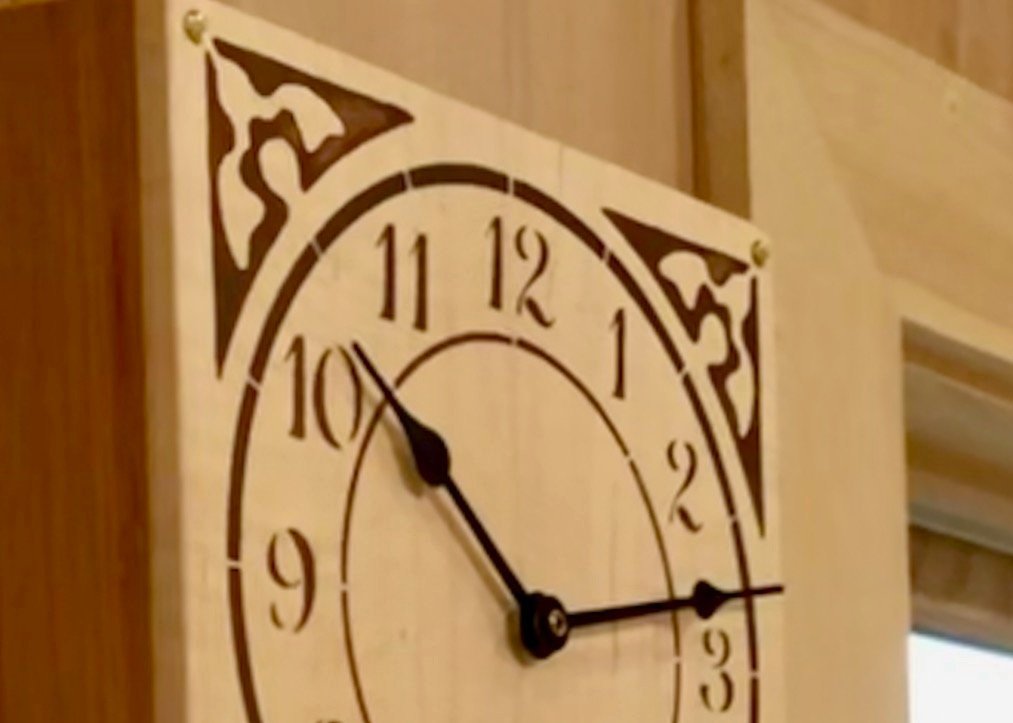
Time to paint with stencils - also a first-time endeavor for me. To learn the tricks I consulted my sister-in-law, Chris, who performs these things well, and her advice helped me sift through the relevant YouTube wheat and chaff. It sounded pretty easy and, in the end, it was. I used an acrylic paint color called brown and a foam cosmetic wedge to dab on the circular face borders and numbers. Stickley’s design also incorporated corner decorations of a pleasing Art Nouveau motif. I tried my best to duplicate this pattern (in a stencil-friendly version) on graph paper which I then sliced into one of the mylar corners of the stencil using a series of increasingly lethal knife blades. This small section of stencil was: mounted onto the clock face; a corner dabbed; rotated by 90 degrees and … repeat x3. I ended up with a few uneven paint patches but these look just fine in gestalt. (Happily, Gustav would approve of that word, if not the unburned wood.)
To assemble one last time, the redwood brackets were screwed into the back and the clock box mounted onto its dowels. The metal plate was “clicked” on to the magnet and then screwed firmly to the backboard. The clock face was attached to the box at the corners with four brass screws. The completed clock box was then removed and the mechanism firmly secured through the center hole using a slim brass nut, the battery was inserted and the hands attached. Finally, the box was re-mounted, the pendulum was hooked to the catch and the completed clock hung onto a screw in the wall.
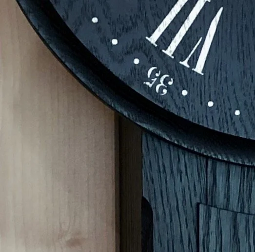
A satisfying clock Project built with uncommon woods and care.
Bat Lord!
“You don’t have to go home, but you can’t stay here.”
That saloonkeeper’s admonition, directed toward late-night bar rats (patrons), applies generally to all types of unwanted mammals. Especially attic-dwellers and in this case, bats! Sparing the subplot details to remain focused on the woodworking topic, my wife and I recently sought to evict and relocate some creepy housemates. To facilitate the transition I thought I might do a small house Project and try my luck as a batlord. [cue: plaintive Romanian strings]
Wha? …
Design
Much has been published on bat house construction but as far as bat house styles go, they are all versions of a single, rectangular plan. For interior layouts bats seem partial to poorly lit, narrow rooms made of scratchy wood. (Not unlike my first apartment, come to think of it.) Popular exterior colors vary by region in the U.S.A.: Dark in the north, Medium tones in the mid-section and White in Arizona. This has to do with temperature control. You see, bats like it hot (80-100 degrees F) and curb appeal for new tenants is all about the ability to collect or reflect solar radiation. After taking in these basic parameters the design work was a matter of selecting a rectangular pattern, defining a reference dimension (e.g., width) and then calculating all of the remaining part sizes accordingly. I modeled my house on the plan put forward by the Massachusetts Division of Fisheries and Wildlife. This design turned out to be identical to the plans found on several other state.gov websites and appeared to be the government housing standard. The dwelling is roughly 18(w) x 31(l) x 5(d) inches in size, containing 4 separate chambers, a rudimentary ventilation scheme and a roof. One source claims that a house of this dimension can accommodate (gulp!) 80-100 bats. [cue: muffled clicks and squeaks]
Did you hear something? … anyway …
Materials
Along with some 3/4 in. pine scrap lumber, exterior plywood (3/4 and 1/4 in.) and a 12 ft. long x 6 in. wide, tongue-and-groove cedar board from the local Box store would be used to construct the living quarters. Rather than pine plywood, I decided to incorporate the more expensive cedar boards for the exterior siding primarily due to their resistance to decay, but the texture is also appealing and, supposedly, the kind of surface bats can’t resist. A shop made plywood/masonite “laminate” using leftovers from earlier Projects would furnish the weatherproof roof. All told with the remaining items (caulk, black paint and some decking screws of various length) new material costs were around $75.00. [cue: silver coins tinkling]
That! Did you hear That? … never mind …
Dimensioning
Cutting all 23 individual parts to size on the table and miter saws was a simple exercise, with many pieces being finished-off using a 25 degree angled “dust cut” to establish the roof pitch. Using the drill press and a 1 1/2 in. Forstner bit, two holes were cut into each of the interior panels so that bats can scramble from chamber to chamber as they seek their preferred temperature zone during the day. The only troublesome step was scoring the 3 interior panels as well as the front and back boards to facilitate these maneuvers. It is recommended that shallow grooves be cut across the width of these pieces, spaced 3/4 of an inch apart, to provide “holds” that can be gripped by the tiny claw-like thumbs protruding from the bat’s wings. Aw, so cute! [cue: screaming teenage girls].
Shh! Okay, I definitely heard something that time, didn’t you?
I planned to make these grooves 1/16 inch deep and one saw kerf in width. And while it would be possible to run these boards overtop a table saw blade set at a shallow height, I considered this to be an unacceptably hazardous move. To execute, one would need to work in an extended posture, applying downward pressure on the piece, above a spinning saw blade until the entire 18 in. board exited the cutting area before letting up … repeatedly … for some 220+ passes. Any execution flaw could result in a kickback that would send the board careening across the shop, or worse. No thanks. Plan B involved cutting these by hand, either with a chisel or a long bladed saw. As luck would have it I was the owner of a late 19th century miter saw contrivance that possessed just such a blade - a 30 incher, in fact! This Victorian device looks like it was designed to make bat houses. The saw comes mounted in a sturdy, surprisingly mechanical miter “box” that provides the means to make accurate cuts at any angle between -45 to +45 degrees from perpendicular. Its specific purpose is to cut the moldings used to frame doors, windows and ceilings, and was part of my great grandfather’s tool kit during his homebuilding days. I can only imagine that in the pre-power tool era long blades were a means of obtaining straight cuts. One or two full strokes with this brute and you’d have a perfectly straight & square through cut. Things were coming together nicely and as I assessed the remaining work I found there were just three obstacles to overcome.
1. I needed to cut across the full width of an 18 inch board and the miter box housing was only 9 inches wide. No problem! I can still use the big saw and make my own panel scoring jig to do the job.
2. While the 125 year old saw blade still had all of its teeth, these teeth appeared not to have been sharpened since “back before the war” - one of the Roman numeral wars. Still, they seemed prickly enough and I might be able to apply sufficient elbow grease to finish off a few hundred passes = several thousand strokes.
3. The job of a miter saw is to perform cross cuts. That is, cuts that are perpendicular to the direction of the wood’s grain. As such, their teeth are both sharpened at an angle and “set” (alternately bent outwards) in a manner to facilitate the crisp severing of wood fibers and subsequent removal of sawdust. Nothing amiss here so far. However, 7 out of the 8 panel surfaces to be scored are made of plywood. And while plywood as a “board” behaves like it has no grain (i.e., the individual layers after being glued together can exert no concerted force in an particular direction) the grain of the outermost ply remains “in play” for the purposes of lightly scoring the surface with a saw. As luck would have it, the plywood I had already cut for the interior panels had the exterior grain oriented East to West, in line with the saw blade. In woodworker’s parlance that would be called a rip cut, not a cross cut. Successful rip cutting is done with a completely different saw blade. I was about to attempt the other type of rip cutting - the kind that inappropriately uses a cross cutting blade. [cue: screaming middle-aged man]
You guessed it, since the saga continues things must have worked-out in the end. No question, the sawing was tough and the saw “dust” instead resembled tiny saffron threads. But something told me that old saw had tackled bigger jobs in its day, and on the plus side I managed to bulk-up my right deltoids. [cue: archival audio, “Hump? What hump?”]
Very funny. Now stop it!!!
Assembly & Finish
The front “panel” was created by glueing 4 cedar boards together and then ripping this assembly to the desired width. I love working with tongue-and-groove boards. They play square. This new panel was then subjected to the scoring procedure and, with properly oriented grain, it sliced like butter. Ahhh!
The State of Massachusetts recommends that every inch of a bat house be painted black and since the upper recesses would soon be inaccessible to all but the most powerful can of spray paint it was decided to darken the interior panel faces pre-assembly. The same goes for the 3/4 in. spacer pieces surrounding the walls and panel tops - make it all black.
Final assembly was a lot like making a layered cake - methodical, almost ritualistic. The ceremony proceeded thusly: clamp the piece in place; frost the corners with calk; screw in a layer of spacers; frost the newly created seams; screw in a scored plywood panel; repeat x3. It all came together nice and solid. The exterior, rear-facing surface was washed with a coat of water seal and then all exterior seams were calked tight. The roof, a composite board made of 3/4 in. plywood glued to 3/8 in. exterior paneling, was cut to size, affixed to the house with decking screws and then caulked about the seams. All screw holes were filled with cedar plugs and then two coats of black latex paint were brushed onto every remaining uncoated surface.
4 chambered bat house from below, in black
This house would hang on the West wall of the Workshop. Not the ideal compass direction, but the only one that made sense after also considering the height and tree cover guidelines. A strong metal hanger was affixed to the back board of the house and secured to the Workshop with a hanger bolt some 13 feet above ground. After adjusting the level, the bottom corners were attached to the siding with screws to prevent sway.
This house is now on the market. [cue: jubilant cheers! from the torch-bearing throng]
Tana Moderne
I know … I am combining languages with this expression, but fusion is what we do at the Red Top Workshop, and “Tana Moderne” is how I describe the latest Project. Here’s the background. Collectively, tana is the Japanese word for “shelf” or “shelving”. When used as stand-alone furniture, these pieces are further identified by their intended use and location: simple tana are the shelves used for storage in the kitchen or shop; chanoya-dana are pieces used for ceremony in the tea room; and kazari-dana are ornamental shelves used for displaying objects in the drawing room or study. I am making a set of end tables for a customer who is fond of Asian decor, and after batting around a few ideas we settled on a multi-tiered, kazari-dana inspired design. Two defining examples of this form, made of mulberry wood, are shown below.
*reproduced from: Koizumi K. Traditional Japanese Furniture, A Definitive Guide, K. Koizumi, Kodansha International: Tokyo, 1986.
Design
The kazari-dana motif goes back some 500 years. These early examples are beautifully delicate and even the so-called “informal” versions are often flourished with intricate carvings. The style was right for this Project, but to match the customer’s modern living room setting we would need to come up with a sans serif version. Modern furniture design generally eschews frills and a moderne version of this recognizable classic was the goal: moderne (Fr.), adj. - [design] characterized by strong horizontal lines and minimal surface ornament. Still unclear on exactly how to accomplish this transformation I happened upon the answer one day while poking around Google. The “prototype” example shown below came from a web auction site with no further information as to age, dimensions or price. It is an unmistakably modern interpretation of a kazari-dana that would anonymously inform this Project on both proportions and modesty. But first the double doors and lacquer finish would need to go. We played around with the overall scale and door design until the customers’ desires were satisfied (seasoned with a healthy dollop of trust on their part). The final request was for two such end tables, one with a doored compartment and the other left open and doorless. Again with the fraternal twins!
Materials
These pieces would be made from black walnut which, like mulberry, is a dark and boldly figured wood. Depending on how bold things looked after mating the individual boards I could apply colorant (stain/dye) to modulate the grain “volume” so as not to drown-out the kazari-dana form. A single, light colored door made of birch plywood would operate on pivot hinges and open with a modern wooden knob. The twin tana would be constructed in the same manner and lack only the compartment feature (i.e., door and backboard). It looked to be a straight-forward build with the wood taking center stage. I purchased 42 board feet of 5/4 walnut and also added a leftover 5/4 plank from a previous Project. These were “rough” grade boards, meaning no additional surfacing had been conducted following their removal from the log, and while the presence of knots and other natural defects could be detected through the fuzzy exterior, the detailed grain pattern and color would only be revealed once my tools got involved.
50 board feet of walnut ready for action.
Dimensioning
To begin, all of the planks were thickness planed to 1 1/8 inch in depth. This operation created a uniform dimension and also revealed the grain, allowing for segregation of board regions by “character”: Showy for the tops and base; Serene for the sides and pedestals; Straight laced for the posts. They were then jointed on one edge to give a square reference. Solving the next puzzle would set-up all subsequent operations on the Project, and that was: Where, exactly, would each of the 42 parts be extracted from? There was over 4,500 sq. inches of 1 1/8 in. deep material to choose from, but this area was parceled within the haphazard lengths, widths and “characters” of 8 separate boards. It wouldn’t do to begin chopping out “cut list Item 1.” from the near end of the nearest board and hope for things to work out in the end - they would not. A more strategic approach was called for, informed by the actual part dimensions and, more importantly, the pairings for the doublets and triplets of smaller boards that would need to be harmoniously joined together to create bigger boards. Indeed, all six of the horizontal surfaces [(base, lower top, upper top) x 2] would each be created from three component boards. The final width of these platforms was 16 in. and, while there are many ways to divide this into three, making them all from uniformly wide (5 3/8 in.) pieces would simplify things both in terms of construction and appearance. The vertical members [(2 sides, 4 posts) x 2] would also need to be assigned within the emerging plat map and similar strategies were employed to locate these. The following checklist helped to account for all parts on twin pieces A and B, and were sized 1 in. longer than required for final dimension.
SHOWY: upper top A (19,19,19), B (19,19,19); lower top A (21,21,21), B (21,21,21); base A (35,35,35), B (35,35,35) = 5 3/8 in. wide stock
SERENE: sides A (13,13) (13,13), B (13,13), (13,13) = 6 1/2 in. wide stock; pedestal A (32/32) (14/14), B (32/32) (14/14) = 3 in. wide stock
STRAIGHT: A (19/19) (6/6), B (19/19) (6/6) = 1 1/8 in. square stock
#= length in inches; (#,#,#) = glued together; (#/#) = paired on the same piece, but not joined
Of course, you don’t need to know any of this. I just thought I would give you a feel for the planning that happens before the cutting begins. Thanks for sticking it out!
To begin, the dark boards were marked appropriately with white colored pencil, cross cut to the desired lengths and then ripped to the requisite widths on the table saw. Since I was building both pieces at the same time, clearly labeling the parts as to what they were and to which tana they belonged was critical. Once the surface components (tops, base, sides) were glued together, thereby converting 26 boards into 10 (i.e., 5 per twin), colored tape served to keep things straight.
Surface boards fashioned.
Each board would have to be refined further to create the mortice sockets, dados and tenons required for assembly. This involved careful measurement followed by the faithful reproduction of cuts within and between tana parts. Making two pieces at the same time gave it all a “production” feel. First, dados (technically “housings”) to hold the side pieces were fashioned in the base and lower top. Since these were so-called “stopped” dados (i.e., stopping short of running across the entire width of the piece) I first created two mortice holes at the start and stop points. A hand held router was then used to excavate the 3/4 in. wide canal in between. I employed a home-made jig to keep everything aligned and performed two successively deeper passes with the router to obtain the 1/2 in. desired depth. Worked well.
Additional grooves were required in tana A to house the backboard of the doored compartment. These were cut into the base, the lower top and the two sides using a 1/2 in. straight bit on the router table. A piece of 1/2 in. cabinet grade plywood would tuck into these slots during assembly.
Both twins would be elevated 3 inches above the floor by a rectangular structure that I call a “pedestal” to avoid the indecorous “toe kick”. Joining the corners together is the only woodworking involved here and since no information could be gleaned from the prototype picture I decided to use a simple box joint (sammai-gumi-tsugi) for this element. Box joints are found on the corners of many antique Japanese furniture pieces, often secured further with small bamboo pegs. It creates a distinctive feature that I would try to emulate here on a chunkier scale. The pedestal members were cut to final width/length dimensions using the table saw/miter saw and then the ends were notched appropriately using a bandsaw and chisel. Pilot holes were drilled into the frame parts where wood screws were then used to fasten the corners during this sub-assembly. In lieu of bamboo, light-colored maple plugs were tapped into place to cover the screw heads and then sawn flush. Prior to final assembly, pilot holes for the pocket screws that would affix the pedestal to the base were created along the frame members.
Pedestals under construction
The upper top is supported by four posts that fit into morticed sockets created on the underside of this part, the topside of the lower top, and the base. It was a pretty routine operation to create the sockets, the only tricky part is to ensure that the smaller, 5 in. posts connecting the lower and upper tops are mounted perpendicular to these surfaces. Since this is a matter of socket alignment from two separate planes, ruler measurements could only get you close. To achieve a more accurate placement I delayed cutting the mortices in the lower top until the very end when a dry-fit of all the other parts would allow me to square things up, insert a “mock” post (possessing a single tenon on top) and then trace the exact position for drilling into the table top. Once the first socket was marked it was created at the mortiser. The “real” post was then trimmed to fit and inserted. The mock post was used to template the second socket, and … [repeat 3x]. The final challenge will be to achieve this same “dry-fit” pose during glue-up.
The posts themselves were fashioned by ripping straight-grained stock to 1 1/8 in. square, cutting the pieces to length, and then creating 3/4 in. square x 1/2 in. deep tenons on the ends using the dado blade on the table saw. The tongues along the top and bottoms of the side pieces, that slide into the housings described earlier, were also created at this time. After removing the surface mill marks, the sharp corner edges of all upright pieces were rounded-over slightly at the router table.
Getting close! A full day was spent card scraping all surfaces to even-out glue seams and remove mill marks acquired during the earlier operations. Then the edges of the tops and base were rounded over at the router table. Two successively deeper passes on both sides of all edges were required to create the desired, blunted bullnose profile in this dense material. Finally, all surfaces were sanded silky smooth down to 400 grit.
Assembly & Finish
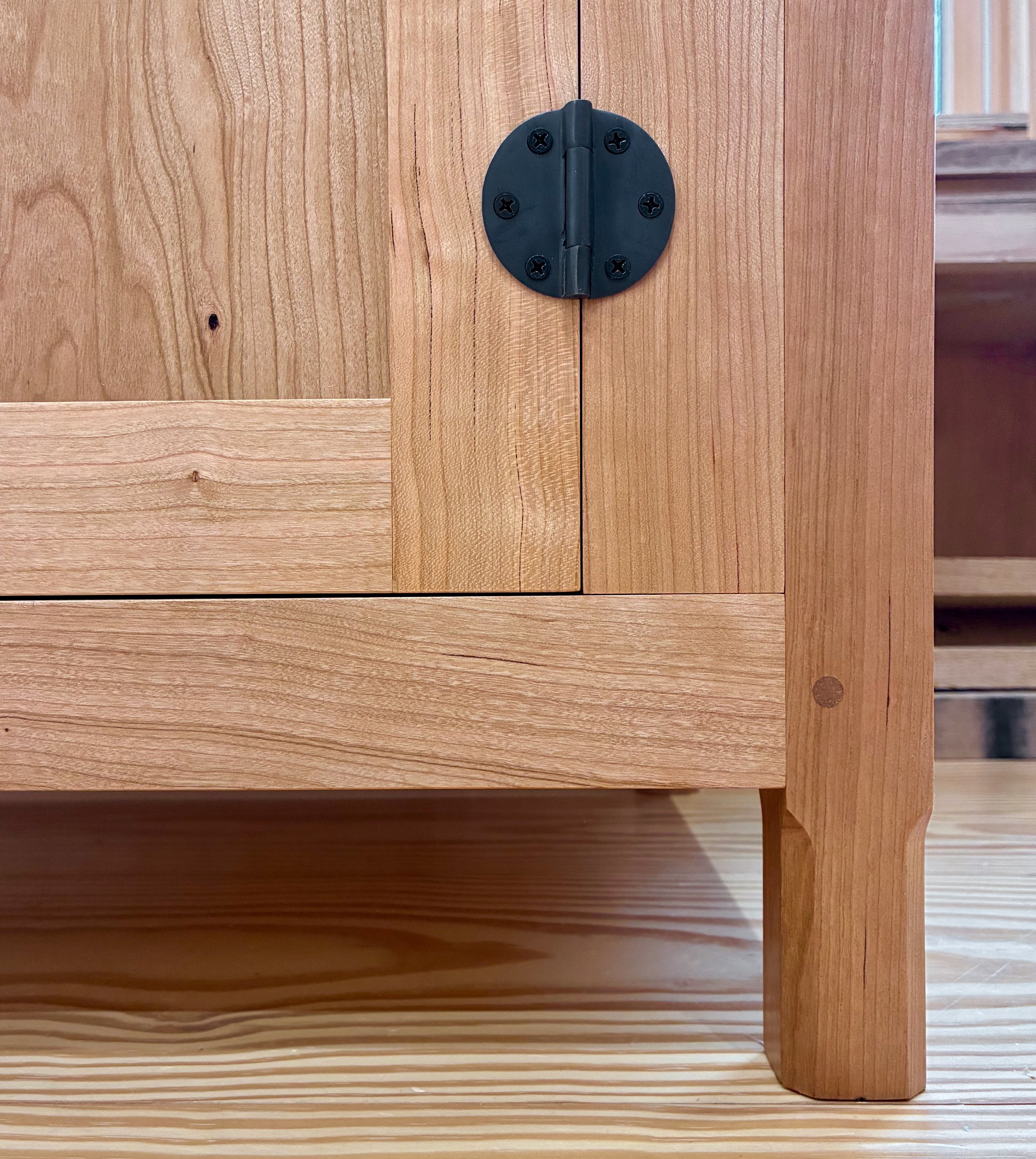
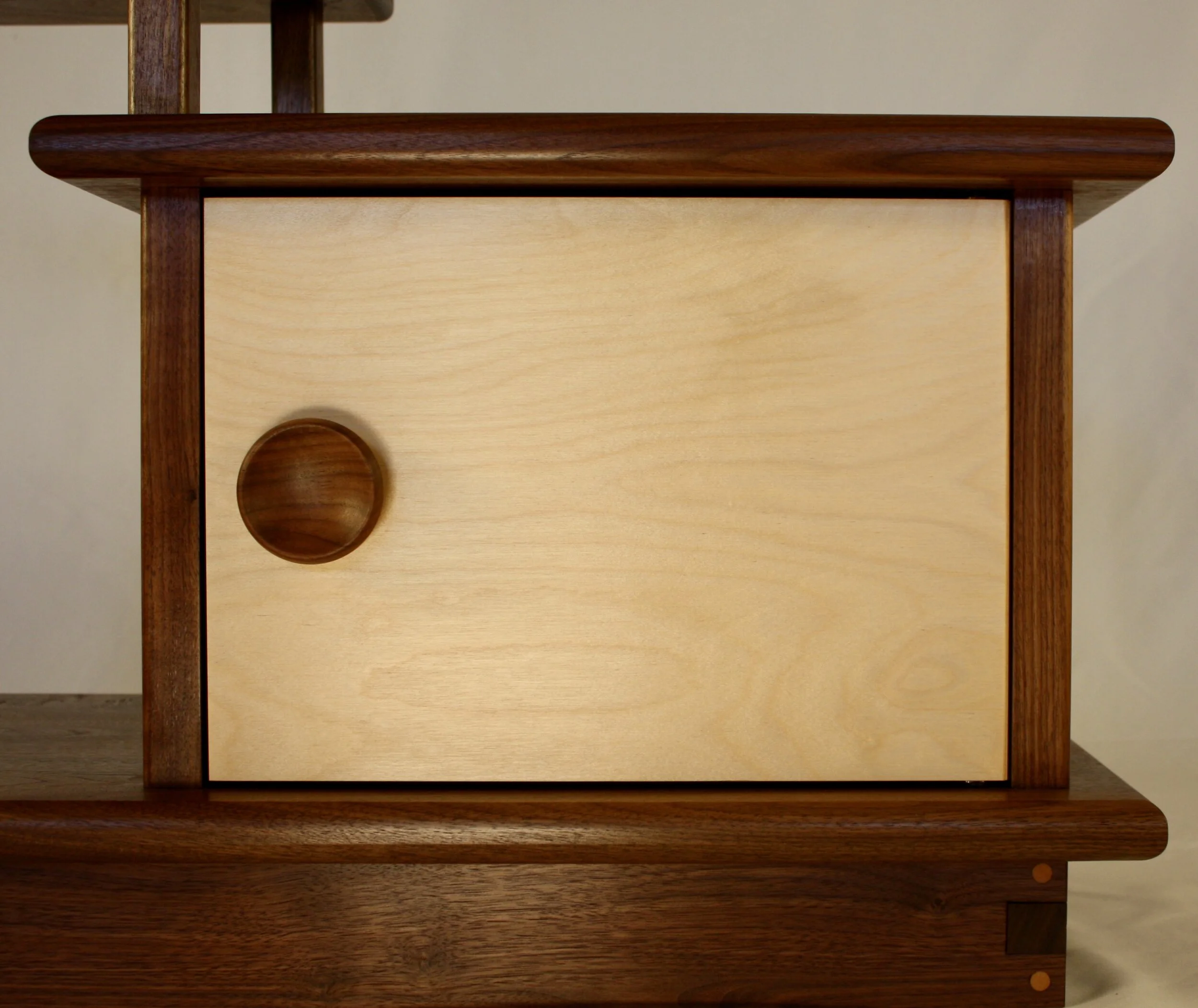
After much middle-of-the-night pondering on how to install that door it was decided to mount the hinge hardware prior to glue-up. Unlike conventional butt hinges which attach to the side frame, the pivot hinges used for this piece “sit” within the top and bottom frames, which, since this is a frameless inset door, translates to the lower top and base. The mounting mechanism is a single hole drilled into these surfaces into which a plastic collar is inserted followed by the metal hinge pin. As the door opens these pins rotate within the collared holes. Drilling said holes 11/16 of an inch away from a fixed side board would not be possible with my hand drill, thus necessitating the pre-glue-up gambit. There is just a little front to back “play” within the housings of the side board tongues and so careful attention to hole alignment would be needed during assembly. To assist during glue-up I constructed a “mock” door of correct height but shortened width. This allowed easy manipulation inside and outside of the cavity, and its temporary installation facilitated vertical alignment during assembly. Following glue-up it could be swapped out for the actual door, prepared according to the finished dimensions. These hinges are easy to work with and provide a nice, hardware-free appearance for mimicking a sliding door design. The over-sized plate knob (in walnut!) would complete the look.
In the end, I decided not to stain the wood but, instead, allow the color variation and grain currents to flow free. More formal examples of kazari-dana found online reveal that, in the high-end homes of old, these pieces were often wildly decorated using gold figures on lacquer. Turns out this shelving was meant to let loose! and the walnut grain now had a real responsibility to put out. Doing what I could to assist, I went beyond the usual gel poly finish in favor of the oil-based products, Seal-A-Cell and Arm-R-Seal. This sealer and wipe-on varnish duo from the General Finishes company are reputed to be excellent for accentuating wood grain while also providing good water & wear protection. They did not disappoint! One coat of sealer was followed by three of the wipe-on varnish. The door and knob were finished in a similar sequence and then mounted into place. Final buffing gave a soft lustrous sheen on these walnut renditions of Tana Moderne.
The Bookshelf Bench
“There is more in the influence of inanimate things than we suspect … upon the development of character”. - Gustav Stickley (1909)
I’ve been interested in Craftsman furniture lately; building pieces and also understanding the story behind this early 20th century movement, more generally known as Arts & Crafts. While there were others involved, Gustav Stickley, a first generation American son of German immigrants, is my hero here. He invented the “Craftsman” style and did more than just design furniture. He realized ideals. Stickley had a vision that, through honest and forthright architecture, interior design and furnishings, an environment could be created for the nurturing of similarly fashioned citizens. In practice, his stated aim was to “make furniture which would be simple, durable, comfortable and fitted for the place it was to occupy and the work it had to do.”* His furniture wasn’t built to impress the neighbors, it was simply intended to fit in and do work. I like that purpose and admire Gustav for branding his efforts so. It is easy to appreciate the direct beauty of his style. This furniture might appear to be timeless, but studying the couple hundred items for sale in his 1909 catalogue, issued at the height of his career and just 6 years before he would declare bankruptcy, one comes to realize the rapidity with which furniture evolves. Yes, everything evolves in response to the influences of pressure. For furniture, the selection pressure of “doing work” means “form should follow function” - no different than for any feature of living organisms (see: Galapagos finches). And “fitting in”, or not, means the threat of extinction is ever present. In the 1909 Stickley catalogue there are many pieces listed for sale that, if not actually extinct some 112 years later, are found only in furniture sanctuaries (aka antique shops). For instance, when was the last time you shopped for a settle? How about a rocking chair, library table, sheet music cabinet, magazine cabinet, smoker’s cabinet, sewing table, toilet table, shirtwaist box, telephone stand, or costumer (a hat and coat stand)? Pretty eye-opening. I can think of a few items “doing work” in homes today that had yet to be conceived in 1909, but not many: coffee table; entertainment center; futon; bean bag chair. Hmmm. It seems we’ve spent the past century innovating in the areas of indoor plumbing, walk-in closets and the World Wide Web to the detriment of furniture … pity.
*Stickley, G. Catalogue of Craftsman Furniture, 1909, p.3.
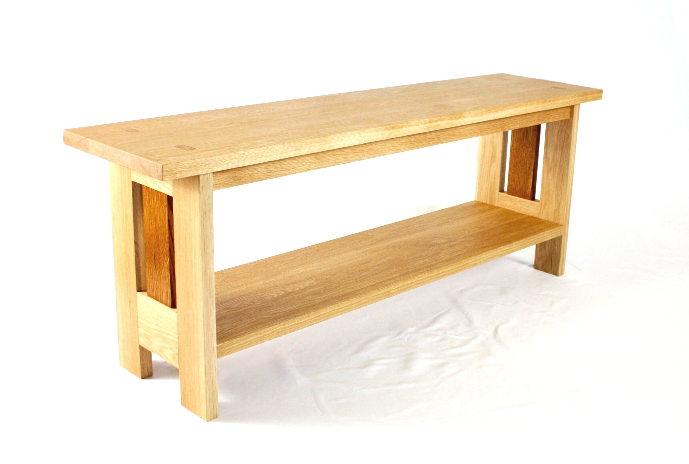
But that’s enough about furniture philosophy. Let’s talk about the latest Project: a bookshelf that can also be used as a bench. This was a request from my older son, Ben, and his wife Allison. They’ve just moved to a new apartment and could use a few additional furniture pieces. A book shelf and some extra seating was needed, and since they have A LOT of books, and comparatively little floor space, they also needed furniture that was ready to fit in and do work. Ben had the notion of a low book shelf that might be sturdy enough to also serve as a seating bench. The stout, utilitarian image conjured by this idea seemed perfectly suited to the Craftsman “simple, strong, comfortable” ethos, even though I could not find a single example in the 1909, 1912 or 1915 Stickley catalogues. Undeterred, it was decided that Craftsman evolution should climb out onto the bookshelf bench “branch” and hope for survival.
Design
Borrowing heavily from structural aspects of the tables and bookcases illustrated in the catalogs, and bounded by customer-supplied dimensions, a basic design was proposed. The plan was to use leg “boards” as opposed to “poles”. This style is reminiscent of Korean table design, and also matches how Craftsman bookcases are constructed. The legs pieces would hold the top with through tenons and their broad torsos could act as bookends. The shelf portion was to rest within dados cut into the leg boards and also be supported with a stretcher underneath. The 48 inch top would enjoy the additional support of “apron” rails which, although not required for the bookshelf function, should help in the bench department. And since this top would also serve as a bench seat, I would need to further stiffen or otherwise shore-up the platform - TBD. The plan was still somewhat fluid at this point and subject to change once the thing started to come together, but it was good enough to calculate the lumber required.
Materials
If it’s Craftsman, then it must be white oak. I picked up 21 bdft of 5/4 S3S material (i.e., 21 board feet of 1 1/4 in. thick boards that had been further surfaced on 3 sides, making for smooth boards of approximately 1 in. final thickness) at my favorite yard. All I needed to do was color-match the four individual boards for the sake of harmony. Simple.
Dimensioning
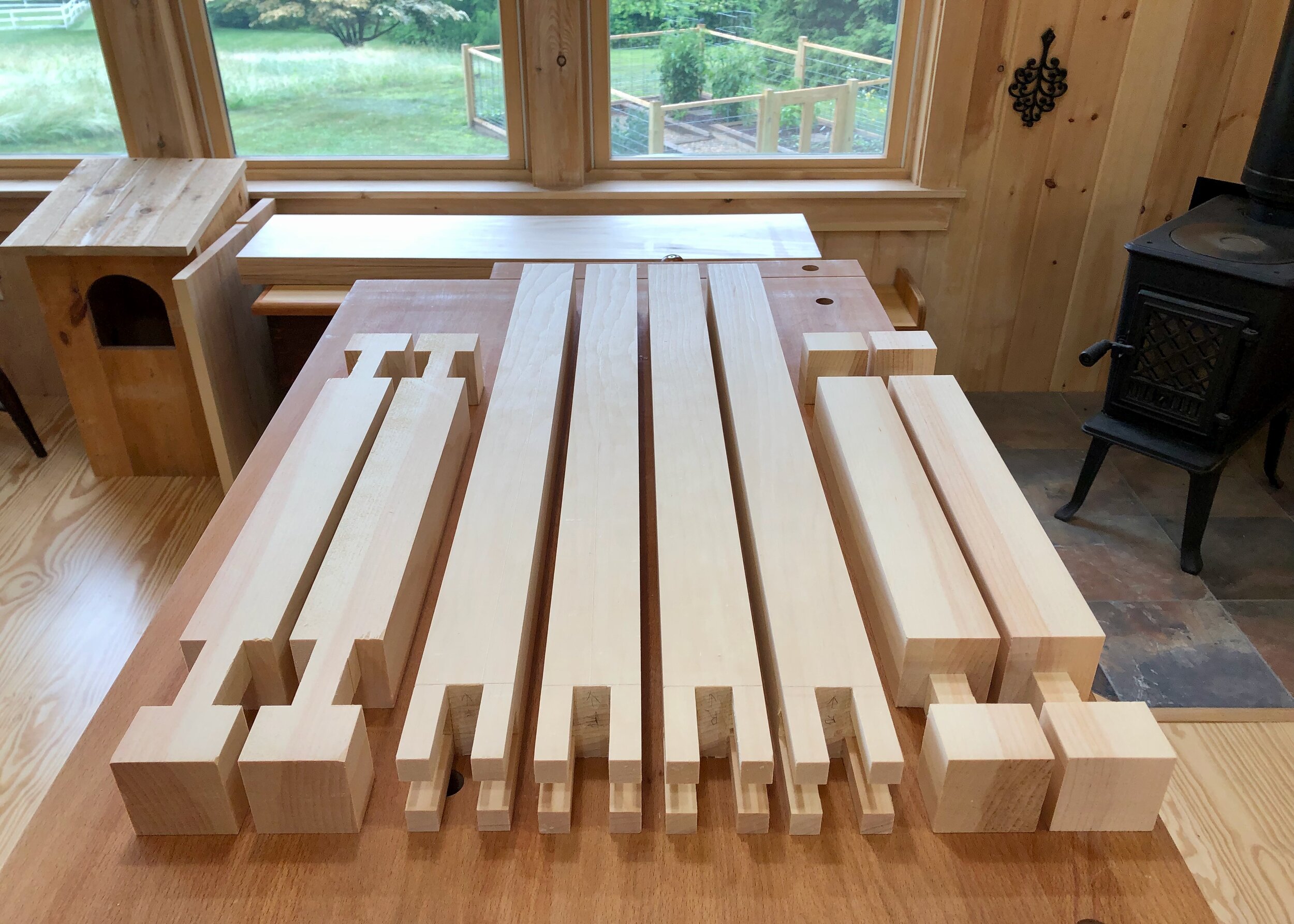
There are a couple critical dimensions in this piece that all relate to aspects of the leg board so it was decided to start there. Instead of using a single plank for the legs, I constructed each “board” from 5 smaller pieces. This makes for a stronger member and one less susceptible to warp. It also provides the opportunity to add some character in the form of material and shape. I planned to make the center “muntin” sections from quarter sawn white oak left over from an earlier project as a design feature. A copy of the shop plan is shown below defining the requisite mortice and tenon cuts that were performed without further description.
The legs would need further modification, but first the shelf had to be completed for reference. The shelf underlying the bench top would be 40 inches in length and 11 inches wide. Three narrower planks were thickness planed to uniform depth and then glued together to achieve this surface. The length was trimmed square at 41 inches and then 1/2 in. rabbets fashioned along each end, and a shallow 1 in. wide dado scored down the center of the underside. These would mate with the leg boards and stretcher, respectively, during glue-up. Next a dado was made in the bottom rail of each leg to accommodate the shelf, and then mortices were cut just below these to receive the stretcher. This effectively sets the book shelf height at 11 3/4 inches. The tenons at the top of the legs, marked by a prior table saw incision, were also completed at this time.
The 48 in. long and 12 in. wide table top was constructed of 3 boards, each specifically dimensioned prior to assembly. The central board would measure exactly 5 inches in width to fit between the two tenons on each leg. The corresponding “mortice” for these tenons would appear at the moment of glue up when the two 3 1/2 inch wide outer boards, previously notched on the table saw, were mated with the center plank. The picture below shows this best.
Pre-assembled table top showing nascent mortices. Biscuits are used to align and join the three boards.
The whole thing could be assembled now and hold-up just fine as a bookshelf, but I wanted to get some aprons underneath the top to support its function as a bench. There were several inter-dependent decisions to be made here regarding “height” of the apron boards, inset from the edge, mortice depth and type of seam with the bench top. Most of these are cosmetic, but the apron height needed to be substantial enough to provide strength while not unduly narrowing the opening for books. I was not able to locate engineering guidelines for this dimension so I chose 1 1/2 inches, meaning books taller than 10 1/4 inches would have to duck upon entry. Mounting the aprons required 1/2 in. deep mortices cut into the leg pieces and these were placed so that the aprons would be inset 1 inch from the edge of the top. Attempting to reduce the number of simultaneous fits during glue-up, it was decided that the top would merely ride on the aprons without any slots to “catch” them. In between the aprons, three 1 in. x 1 1/2 in. oak boards were inserted for extra rigidity under load. I could have cut additional dados into the apron sides to secure these but felt that they could be held in place by pocket screws just as well and without suffering any wood removal along the slender beams. Feels stiff enough.
Dry fit (top removed) showing three oak board inserts pocket-screwed to the aprons.
Assembly & Finish
Getting close to glue-up, but I needed to first clean-up the surfaces and remove the mill marks, smooth out the glued seams on the shelf and soften the sharply angled edges. This was done with a combination of hand planes, card scraper and sandpaper. It took a good half-day to complete the operation (and the top is still undone) but once in the proper mood I find it a satisfying activity to bring out the best in these wooden parts that up to this point had been handled rather harshly.
I also played around with finishes for the two muntin pieces at the center of the legs. Once glued together, Stickley would have subjected the entire furniture piece to the fumes of ammonia for a day or two, allowing the caustic gas to chemically react with the tannin components of white oak. This process uniformly darkens the color of wood and it was his treatment of choice. He used a few other finishing schemes, but the beautiful, deep brown color we associate with Craftsman/mission-style furniture is the result of ammonia fuming followed by a rub down with furniture wax. I was happy leaving the oak bookshelf bench to patinate naturally over time, but thought I might try to duplicate the rich brown color on the two muntins as an homage to Gustav. I flirted with fuming and will certainly use this procedure someday, once I create a chamber to safely do so. Instead I chose the dye/seal/stain/varnish process, best described by Jeff Jewitt, that allows us counterfeiters to spend three-times the effort reproducing the look of fumed oak. It works particularly well on quarter sawn wood grain and I had played around extensively with this during earlier picture frame and clock Projects. Here’s how it goes: after treating the wood with water, allowing to dry and then sanding the raised grain, I used a “medium brown” water-based dye to color the wood; followed by a coat of oil-based sealer; treatment with an “Early American” colored wiping stain to darken the pores; and finally a satin-sheened wiping varnish to finish. I liked the look of the test piece enough that I then spent the next four days treating the real pieces. (Gotta make me that fuming contraption soon!)
With all of the pieces properly prepared it was time for glue-up. This involved assembling each glue-moistened leg piece together and then fitting these constructs to an upside-down shelf and stretcher. Once clamped, the entire piece was flipped upright and the apron section carefully banged into place with a mallet. After a check that all of the matching length dimensions were indeed equivalent, seams tight and angles square, the middle top section was inserted into place, glue was applied to the biscuited edges and then the outer boards were tapped in tight. Desktop fasteners were used to firmly mount the top to the frame, the clamps repositioned during a final measurement check and the glue allowed to do the rest of the work overnight.
15 pieces all fitted, glued and clamped.
To complete the top I needed to first trim the protruding leg tenons with a flush-cut saw and then shave them even closer with my new block plane. The entire table surface was touched-up with a hand plane and the remaining mill marks erased with the familiar scraper/sandpaper duo. The ends of the three mated top boards had been left uneven and so these needed to be trimmed square with the track saw, leaving a 3 in. overhang on each side. All sharp edges were then softened and the entire piece worked lightly with 220 grit sandpaper to remove residual clamp marks. Finally, four coats of gel polyurethane varnish were applied to complete the bookshelf bench.
Got Character?
The Rice Chest
On to the kitchen! This room in our 70 year old Ranch home is cozy & functional but the one thing we parted with when we moved from our former Colonial is pantry space. That’s an amenity not truly missed until you have to live without. We manage with a large free standing cabinet next to the refrigerator that is used to store snack foods and other essentials. It also serves to conceal the various 5-20 lb. bags of rice that sit upright on the floor nearby. Rice is used almost daily in our house and, for all that they contribute, these bags deserve a better life. Once upon a time in Korea, uncooked rice (ssal) had its own chest in every kitchen. The ssal tuiju was heavy, purposeful furniture tucked away somewhere far from the fire and watery areas where the cooking went down. The picture above was taken at the Namsangol Hanok Village (Seoul), in the kitchen of one of the mid-nineteenth century homes maintained on the grounds of this special place. It would have held several bushel of grain in its day, dispensed with a scoop after lifting off the top, and thus the inordinately robust construction. The joinery beneath the lid is a derivative of Korean post & beam house construction methods. I’m not sure of the Korean name, but in the West we know it as a “castle” joint, for the pre-assembled post portion resembles the crenellations of a castle tower. If you break it down, each leg is joined to two intersecting cross members by a ‘T’ bridal joint on top of another, perpendicular ‘T’ bridal. This allows a half-lap joint to be formed between the cross members, themselves, deep within the castle tower (read: strong). A chance to try-out this joint was what moved a new rice chest up to the head of the “do list”.
Castle Joint in diagram
Reproduced with gratitude from j-woodworking, one of my favorite YouTube sites. Check him out. He is inspirational in how he teaches without the spoken word.
Design
There was only one spot in our kitchen for a new piece of furniture and this would replace a plant stand. The maximum width dimension for a piece in this spot is 21 inches and with a height of approximately 26 inches that would mean a ‘portrait’ rather than ‘landscape’ posture. While this orientation would certainly do the job, I was unsettled by the potential lack of authenticity. All of the rice chest examples in my books and online were at least as wide as they were tall (see above). However, while scanning my phone for pictures of additional examples I came upon another setting from Namsangol where several pieces had been clustered in a corner and there in the shadows was a small tuiju, probably used for red beans, with the exact proportions I was looking for!
Exemplar grain chest standing proudly next to big brother (oppa).
Design of the carcass from this photograph was simple. The challenge came in maintaining the look of a “chest” while re-engineering the piece to be more of a “cabinet”. We needed a solid storage place that would provide easy access to the various rice bags held within. Removing a top lid and then reaching down to pull up a 20 lb rice bag was not the answer. In fact, it was decided to fix the top permanently to the carcass and convert the front panel to a flush-mounted drawer front. The hope was that this piece would capture the essence of a centuries-old rice chest on the outside while doing its best to enable modern living on the inside (where it counts).
Materials
Pine is the wood most often used for the framework of rice chests. The panels have been made from a variety of woods but I decided to stick with pine throughout. I had some thick, clear grain Eastern White pine (Pinus strobus) in the shop that could work for the 2 in. square leg and cross members and some 5/4 and 4/4 material of the same species for the top and side rails, respectively. Some nice wide planks of 3/4 in. New Zealand pine, found at a local builder’s supply, would be used for the panels. Pinus radiata (so-called New Zealand pine) is actually a tree native to Monterey County, California and a couple of the small islands off Mexico. It was introduced to Australia in the 1850s, perhaps by California miners seeking better finds in the Australian gold fields. Like many “invasives”, it actually grows better in its new home and is extensively farmed throughout Oceania for lumber and pulp. Good on ya, mate!
Dimensioning
The top of the cabinet was made by glueing 1 1/8 in. thick pine boards together to make a 21 x 21 inch surface. This dimension defines the length of the castle joint cross members which will be made 1 in. shorter and mated with 25 in. long legs. The stock for these parts were cut from a large pine plank and the joint elements fashioned as follows. The two key dimensions for creating this joint are the leg thickness and the space between the castle’s battlements. All of the joint parts will be made to either straddle or fit within these two dimensions. The legs were made to be 2 inches square - easy. Many designs use 1/3 of this dimension for the width of the “valley” between battlements, but I wanted the “waist” of the corresponding cross member to be no narrower than 3/4 inch and so I fixed that number as the other critical dimension, making the “forks” 5/8 inch square, by subtraction. The valley between the battlements needs to be a full 2 inches deep (and true) so I decided to use my tenoning jig on the table saw with a dado saw blade. This store-bought contrivance allows one to accurately & safely pass an upright part through a table saw blade. Once adjusted properly so that the 3/4 inch blade stack exactly bisects the leg it was a simple matter to make the grooves in eight passes (2 per leg).
Cutting grooves on the leg at the table saw with a tenoning jig and dado blade.
The four cross members were also fashioned on the table saw using a dado blade and a cross-cut sled. As with the legs, a small prototype piece (aka stubby) was first marked, cut, the blade & sled then adjusted as required, then cut, adjusted, cut again until a good fit was obtained. Its extra work but it gives confidence that the “production run” will be successful. Now, this operation removes A LOT of wood (as sawdust) and it might have been more efficient to do some (all?) of the cutting on a bandsaw but I felt the dado/sled set-up would be more accurate and since I was using pine (i.e., a soft wood) I could hog out the slots in a single pass. Were I using a hardwood that necessitated several passes of increasing blade height to make a single slot I might have used a different approach. It’s always good to have options and to consider them before setting up for the cut.
With all of the joint dimensions established I still needed to treat the ends of the cross members in some manner to convert the block shape into something more appealing to the eye. It’s a defining feature for the “look” of traditional rice chests. Sometimes the ends are simply chopped at an angle but I like the rounded look better and it should be just as easy to create on the bandsaw. While I could have traced a template and made all 8 cuts freehand I thought maybe this would be another job for my circle-cutting jig. Since its construction earlier in the year, this simple device has helped to create the Stationery Chest and Owl House, where in each case the circle was discarded in favor of the surrounding “doughnut”, and also the Round Tabouret, where the “hole” was the goal. To achieve the desired curve I would need a radius of 1 7/8 in. This would place the pivot point inconveniently within the waist of the bridal joint and so I fashioned a separate platform that could rest on the jig and pivot in the desired arc while carrying the piece to be cut along for the ride. Chalk up another one - it worked great! I once saw a YouTube short titled something like “Give a redneck a table saw and he’ll make a bowling ball” which went on to show how a jig could be made that would allow a large block of wood to be turned into a spherical shape the size of a bowling ball on top of a spinning saw blade (shiver). I’d hate to see what type of gewgaw might be fashioned by an innovator from the South using my versatile circle-cutter (shudder).
The only pieces remaining were the 4 rails, the 4 side panels (one of which will serve as the drawer front) and the floor board. The rails would be cut from 4/4 white pine and secured to the piece with tenons into the legs. You know the sequence: first measure for the corresponding mortice in the leg, cut these with a mortiser (1/2 in. wide by 3/8 in. deep) and then fashion the tenons on the rails using the dado blade and cross-cut sled. In the process of cutting the mortices I also created a 5/16 in. wide by 3/8 in. deep groove (dado) in the legs to receive the side panels. After morticing a square cavity at both ends of the panel grooves I used a 5/16 in. bit on the router table to dig the “canal”. Worked great! and reminded me how smoothly things usually go when working with pine.
Next came the first dry fit. The rails squeezed snugly into the legs and held the castle towers rigid. Gratifyingly, all 4 legs touched the ground at the same time, too! The cross members were a tight fit. They’ll probably seat down properly with some sanding and mallet assistance when the time comes, but I did not want to risk seizing things up at this stage so I left them to the side. This dry fit was simply to mark the exact spot in which to cut dados into the top of the rails and bottom of the cross members to receive the bottom and top of the side panels, respectively. These were then created on the router table, as before.
Time to make the panels. Although extensively mill-marked (i.e., little ridges spread across the surface from the final operation at the saw mill) the New Zealand pine was uniform in depth (3/4 in.) and satisfyingly “flat” so I decided not to do any further thickness planing. Instead, one long edge was jointed true and the other edge created by ripping on the table saw to 11 in. in width. The finished panels needed to be 13 5/8 in. wide and so 2 5/8 in. strips were ripped from additional stock, all pieces cross-cut to the desired length and then glued to augment the width of the back and two side panels. The drawer front piece, measuring 16 1/2 x 13 in. would need to remain straight and true without any assistance from carcass framing and so I chose to rip three smaller pieces and edge glue them in opposing grain directions with the hope of thwarting warp. A rabbet (5/16 in. wide by 3/8 in. deep) was then created about the perimeter of the back and side panels to fit the earlier fashioned dados. This could have been accomplished in several ways, and I chose to use the dado blade/table saw mode rather than the router route. Once completed, a second dry fit predicted all would go well during the glue-up.
Even though I was going to build a pull-out shelf/drawer I still felt the need to make a cabinet bottom. The bottom is not necessary for structure or function but it should keep out dust and, anyway, no rice chest of mine would be going “commando” in the kitchen. I used 1/2 inch birch plywood for this element which sat in a dado cut into the bottom rails. The only trick was notching the four corners of the plywood to accommodate the legs, which was readily performed on the bandsaw using stops and a fence. Done!
Nice work, stubbies! Your faithful service has spared you from a fiery fate.
Assembly & Finish
This pine was very soft and so to prep the pieces for assembly I used a card scraper to even-out the glued edges on the panels and then sandpaper to clean-up all of the surfaces: 120 grit with an orbital sander, followed by 150 and 220 grits hand sanding. I put off cutting the top to final dimensions until the carcass was glued-up and I could then experiment with different overhangs and edge treatments. One final dry-fit revealed that I had goofed earlier in the construction of the castle joint. I removed too much wood, essentially eliminating the half lap joint between the cross members at each corner. I understand how this happened and it is not worth recounting. No worries! The double bridal joint is still more than strong enough and my castles now have some secret chambers within, oh well.
In fact, as I was doing this last dress rehearsal, assembling parts in different orders and taking careful notes on each step for future reference, it dawned on me that since the floor and side panels would be left to float in their dados and the castle joint would be plenty tight when seated, the only joints receiving glue would be the mortice and tenons in the bottom rails. This dry fit started by sliding the floor into the rails, which were mounted loosely into the legs so that the side panels could be dropped into place. Once this assemblage was pounded and clamped tight, the accumulated frictions held it all together quite well. Now, in previous attempts I had only dry fit one cross member into one leg at a time, in order to trim surfaces and confirm fit within a single joint. With an all-but-complete chest in front of me I decided to see how the cross members would fit when mounted into two legs at the same time. Things proceeded well and before long I was tapping the final member into place. The full 2 inch mating surfaces of the Castle joint puts a severe constraint on all pieces to align perpendicular to each other. So much so that the unglued rails held solidly, no matter how much I tried to tease a gap between them. This finding, and the realization that disassembly would involve the difficult chore of pounding the Castle joint open by striking at the four rounded corners, prompted a declaration of victory. No glue for you!
On to the drawer. To control the movement I decided to use old-fashioned roller hardware from the 1940’s called GO-EZ slides, as opposed to the newer, fully enclosed models or the even older wooden rails. My cabinet is not a standard cupboard depth and, with a hacksaw, this style of drawer slide is perfectly customizable. The roller track would support a drawer-bottom “shelf” made of 3/4 in. plywood to which a 3 in. pine backboard had been glued. Mounting this within the rice chest was pretty straight-forward, allowing 1/16 in. clearance on each side. A 3 in. tall “front board” was then mounted to the shelf and the drawer front panel affixed to this using cabinet fasteners. The drawer glided in and out smoothly even when tested with a mock handle up near the top. I was afraid that pulling on the drawer some 10 inches above the track would cause it to rock and then jam, but all seems well (whew!).
The hardware on original rice chests consisted of a lock to secure the removable top. This was not needed in my cabinet version; instead I required a drawer pull. You will find that all of the pulls on traditional Korean furniture are of the single- or double-hook variety where a hanging ring or semi-circular piece of metal is lifted and then pulled to open the drawer. While these would work on my rice chest, I felt they would be awkward to use. It seemed that a fixed drawer pull, like those typically used for kitchen cabinets/drawers would be a more natural fit. I perused the endless variety of cabinet pulls on the internet for something primitive; something that looked like it might belong on this, admittedly, novel furniture piece. A mixed iron and wood handle was chosen and then ordered, following approval from kitchen management.
Finally, the top was cut to leave a 1/4 in. overhang, (20 1/2 in. square) and the edges sanded. It would be affixed to the cross members using desktop fasteners as the final step once the drawer handle was installed. Waiting for the new pull to arrive gave me time to treat the wood with a coat of linseed oil. I wanted to achieve a bit of seal while keeping the surfaces as raw as possible and allow sunshine and daily handling to impart an “honest wear from use” look - no stain, no gloss. In fact, I did not apply any finish to the cabinet interior to avoid off-gassing odors that might taint the rice.
Installation of the handle and top produced a 21st century rice chest with hints of old and new. A time-tested design enriching modern life.
Twin Tabourets
I know … I had to look it up, too. Tabouret is one of those French words with several meanings (and spellings) that you have to coax from context. It describes my new Project, and since I had no intention of making a: 1. low one person stool; 2. embroidery frame; or 3. drum; it had to be 4. small, usually portable stand. That’s the one! - two, actually. My little sister, Lisa, had recently made a polite request for a couple of “small, usually portable stands” to be used in her home office and, of course, I was happy to oblige. In truth, I only happened upon the high falutin “tabouret” term when searching for table design ideas, but if you grew up with the lovely Lisa Renee Goulet you would agree that her tables require le raffinement. Lisa also stipulated that the tabourets be distinct from each other. Maybe the fact that she had to grow up with identical twin brothers (me & Mike) accounts for her aversion to symmetry? Anyway, fraternal twin tabourets it would be.
Design
The winning designs were found in a book of furniture plans* compiled from The Craftsman magazine founded in 1901 by Gustav Stickley, a leader of the Arts and Crafts movement in America. I had had my eye on several of the Stickley pieces in this book (clocks, desks) and was happy to now have the occasion to take action. One article, originally from the April 1905 issue, described plans for “two tabourets almost identical in construction” - bingo! The article also mentions that these would “be a useful addition to any room for the purpose of holding a jardiniere”. (Ever notice how sterile our vernacular has become, some five generations removed from the great influx of European immigrants?) Anyway, I looked it up and “jardiniere” is another French word that describes either: 1. an ornamental pot for plants; or 2. a garnish of mixed vegetables.** So this should give Lisa plenty of options. In fact, her twin tabourets were intended to support specific objects in the office and so a bit of customization was warranted. The request for a small table to support a fountain could be made almost exactly to the “Round Tabouret” plan, whereas a second table of sufficient height to support a lamp behind an upholstered chair would require stretching the dimensions of the “Square Tabouret” plan by 7 inches. Also, the original plan called for a square top, but since this was to be positioned in a corner of the room, a triangular, three-legged design was proposed. Some quick sketches were made but these were no better than my doodles from the original article.
* G. Stickley Making Authentic Craftsman Furniture: Instructions and Plans for 62 Projects Dover, 2018.
** The comedian Steve Martin famously remarked that “Those French have a different word for everything.” Recently I’ve concluded they have words for some things which they reuse on all the rest.
Materials
Since I had been making furniture for a year under the Red Top and for three years, part-time, in my former workshop I had quite an accumulation of plank end-cuts (aka leftovers) from all of the usual hardwood species . I was also the keeper of some antique wood passed down two generations from my grandfather Otto. Surely, some combination of materials from this collection could be used to make these small items. What I was searching for was a theme to connect the two siblings. Since the legs of the two would be made in the same manner, I chose the same wood for both: redwood, obtained from some very old, 2 x 4 in. planks salvaged by Otto during the demolition of something, based on the substantial fractures sustained along their 12 foot lengths. Anyway, it looked like the legs could be excised from between the cracks and these would give each piece a nice, dark foundation. The table tops are what distinguish the pair and I needed the wood to impart personalities here. For the smaller, round top I chose a striking piece of hard maple, leftover (I hope) from an upcoming desk Project. The brown grain flowing wildly through the cream colored summer wood is a pattern only Nature could conceive. The triangular top would be made of cherry, my favorite wood to work with and one whose color should pair nicely with the redwood below. Its grain is strong but not flashy. This piece’s flair comes from performing its function on only 3 legs (show off!).
Dimensioning
You know what we say in the workshop, “no grain, no pain”. Okay, what we mean to say is that “grain is a pain”. Okay, okay, nobody’s been heard actually saying those words, but I’ll bet they’ve been muttered out of earshot. Grain, the alternating layers of spring and summer growth, is what makes wood such a special building material, imparting strength as well as beauty. When things go well during a tree’s development the grain flows straight and parallel. This is most evident in the mature lower trunk. Higher up, where branching, the search for sunlight and wind effects take their toll, the grain becomes much more interesting. Wood derived from this area is where the action is at! How much action the woodworker wants to experience is up to the decisions made at the lumberyard when they select the species and, within species, the specimen board they chose to work with. Forewarned is fair-warned.
Now, power tools with sharp blades generally laugh at all wood grain. They slice through it without much notice of the divots left behind, descriptively referred to as “tear-out”. And, with some strategy to dictate the proper direction of feed into the tool, most wood can be dimensioned on a jointer, thickness planer or router with minimal tear-out damage. However, the manual version of these machines, hand planes in all of their varied designs, cannot be mastered until one appreciates and anticipates the effect of tool orientation with respect to grain. This is easy to understand in theory, but takes experience to truly know how to execute without flaw - take it from someone who does not yet truly know.
I diverted toward thoughts on grain as the wood chosen for the round tabouret top, hard maple, represents one of the most challenging materials to dimension smoothly. Tough fibers, densely packed and weaving in all directions are what distinguish this wood. To achieve the 15 inch diameter of the top, 3 boards (all derived from the same plank) needed to be edge-glued together. Use of my handy biscuit joiner works well in these applications and, while modern wood glues are reported to fasten boards on edge with no need for further “doweling”, I prefer to use biscuits when constructing table tops or any surface intended to support a load. Prior to assembly I attempted to align the grain in these three boards to facilitate subsequent hand-planning. The intention is to have the grain running “up” and through the surface of the board ahead of the plane blade to eliminate the heartbreak gouges of “tear-out”. However, the issue with this piece of maple is that the grain undulated and was variously up, down and sideways throughout the 16 x 16 in. surface. My cautious attempts to even-out the glued seams with a #4 smoothing hand plane worked well in spots but created pits and rough patches whenever the grain took a dive. It basically made things worse. So bad that I decided the best course for correction was to get out the router plane jig and zip-off the top 1/16 in. of the surface. This worked well and produced a slightly ridged terrain (think: newly mowed lawn) that could be smoothed readily with an orbital sander - much better than its precursor (think: pot-holed asphalt). Better craftsmen could have done the job with a hand plane and I aspire to be that craftsman, one day. The glued top was left in a polygon shape as the flat, square edges would facilitate subsequent manipulations. It would be liberated as a circle in the final cut.
By comparison, the cherry wood used for the triangular top appeared courteous and well-mannered. Three boards were also required to achieve the 12 in. altitude dimension. I needed every bit of depth from these 5/4 boards which had already been thickness planned and didn’t dare risk another session with the router plane jig, so once these were glued, a preliminary surfacing to even-out the joints was done with the orbital sander. At this point the triangular top was cut to the final dimensions. I used my track saw to create the two long sides and then chopped off the vertices with the miter saw to leave 2 inch “nubs” at the corners.
Cutting the sides of the triangular cherry top using a track saw.
The next step was to create mortices (rectangular holes) in the underside of these tops to receive the tenoned legs. The original plans called for “through tenons” where the leg piece would protrude all the way to the upper surface of the table. This is a stronger construction method than the use of “blind” tenons, which stop part-way into the table top, and one that I would have chosen to use if the tables parts were all made of the same wood species. However, since the table tops and legs were intentionally made from different materials, I thought it best to let each element “represent” without interference from the other. It’s a design decision with minimal impact on structural integrity.
The order of operations when making this joint is to decide on the tenon dimension, cut the mortice openings accordingly, and then fashion the tenons to fit exactly within the opening. While the legs for each table differed in thickness, I decided that a 1/2 in. square tenon that was also 1/2 in. in length would do the job for both. The position for the mortices were marked on the underside of each table and then cut using a mortiser. This handy power tool is simply a direct-drive drill press designed to hold a square, hollow chisel in which resides a coarse drill bit. It allows one to accurately cut square holes in the same manner as a drill press is used to bore round ones. As a power tool the mortiser replaces the chisel & mallet. The bottoms of the tops were morticed without incident and the interiors cleaned-out smooth with a chisel. Now on to the legs.
Morticed cherry top
As mentioned, by some mysterious trauma the antique redwood 2x4’s had suffered oblique fractures along their length and so the first step in preparing the legs was to remove the cracked sections using my miter saw. This left 5 segments of varying lengths, sufficient to produce all of the leg and cross brace pieces (stretchers) from the same stock. The segments were in turn, jointed “flat” on the 4 in. surface and thickness planned to remove the rough, discolored wood along the opposite face. This produced boards with parallel sides, which were jointed again on one of the 2 in. sides. Stock prepared in this manner can be easily turned into square leg pieces by sequential passes through the table saw using the rip fence set up one leg’s width from the blade. Rip, rotate 90 degrees, rip again.
While a 1/2 in. mortising bit was used on the tabletops, upon clean-out the dimension becomes a bit wider than that. The corresponding tenons will be cut using a dado blade stack on the table saw using my new cross-cut sled to register the piece and ensure consistency within and between legs. In the event, the dado stack was built up to a blade width of 1/2 in. and raised to a height “x” above the cross-cut sled such that (2x + 1/2) = width of leg in inches. A stop was clamped to the back of the sled at the edge of the saw blade opening and this allowed the top of each leg to be tucked against the stop block and cut in 4 sequential passes: 4x(cut, rotate 90). Of course, I made a test piece first to confirm dimensions of the final tenon for each leg type. I tried to make them just a bit thick and then sanded them to get a snug fit into the mortices. Worked well.
Next, mortices would need to be cut into the legs to receive the through tenons of the stretchers. The set-up is the same as for half-tenons only a “sacrificial” board would be placed underneath the leg to receive the mortice bit as it bore through. This saves the bench from getting cut but does not completely eliminate tear-out from the exit hole in the leg, thus it is important that the “show face” of the leg be positioned to receive the mortice bit at the start of the cut (i.e., facing up). This operation went well, applying a 1/4 inch bit incrementally for a series of cuts to achieve either a 1 1/2 or 1 3/4 in. mortice “slot”, depending on the table leg. Afterwards, the openings were smoothed using a chisel.
The stretchers were prepared from leftover redwood: jointed; resawn; thickness planned to 3/8 and 1/2 inches in depth for the small and large table, respectively; and then ripped to 2 1/2 inches in width. Again, using the dado blade and sled, the tenons were cut on one side of each stretcher to the proper 1/4 in. thickness and a length that was 1/2 in. longer than the leg width. With the tables upside down and legs akimbo (see above), the half-cut stretcher could be laid in place alongside the leg and marked for the second tenon cut. This exact marking is important and will correct for any deviations that may have occurred during the table top morticing step. The second tenons were dadoed to size and all pieces then taken to the bandsaw to create 3/8 in. shoulders.
The pattern and mode of intersection for the stretchers for both tables were taken from the design of the round tabouret (see renderings above). The desired curve was sketched on card stock paper, cut out and used as a template to mark one stretcher for each table. The stretchers pairs were then placed on top of each other, taped together and the pattern cut out on the small bandsaw. Some sanding with a course drum bit mounted on the drill press and a little hand polishing made for a smooth curve which then needed to be notched in the center to allow intersection. The notching was easily done on the bandsaw by first un-taping the boards, flipping one board 180 degrees, and then re-taping them together followed by marking the center. Two incisions, one-half of the width at the centerline (3/4 in., in this case) and one stretcher’s thickness apart were made with the bandsaw. The notch was then chopped out of this with a hand chisel. For the three-legged stretcher assembly, one stretcher was then cut-off 1/2 in. past the intersection point.
Redwood legs and stretchers cut to final dimensions
Finally, it was time to cut the round top. This was a satisfyingly easy step using my home made circle-cutting jig on the small bandsaw. This jig aligns a pivot point with the front edge of the saw blade. A small indentation is made in the board to be cut at the center of the desired circle and the board then plopped on top of a screw protruding at the pivot point, previously inserted one radius length from the blade. With the saw running, the jig is slid into place, “loading” the board and positioning the saw blade at the circle’s edge. The board is then rotated on the pivot above the fixed jig and a perfect circle is sliced.
Last was a treatment of all edges. The bottom edge of the triangular top was chamfered, as were the three legs using the appropriate bit on the router table. The legs for the round table were similarly treated using a round-over bit to smooth the edges. In both cases I opted to not treat the leg edges in the area of the stretcher joint. I wanted there to be some indication of purpose to this region, much like the flare of a knee or elbow joint along an extended limb. It’s subtle but I hope it works. All pieces were then hand sanded down to 220 grit.
Assembly & Finish
The glue-up was a straightforward affair, given the nature of tenon joinery and perhaps some accumulating experience on the assembler’s part. I decided to use gel polyurethane varnish for the finish. Even with a satin gloss it should add life to all the woods and give a durable waterproof protection to the tops, but not blotch the cherry as an oil might. Four days of wipe/dry/repeat and voilà! Les tabourets sont finis!
With Love …
The New Garden
The main character in this blog post is actually a fence, but please read on.
I grew up in the countryside of rural Michigan on the family farm - never fully “immersed”. The crops raised were wheat, corn, navy beans and sugar beets but the job of raising them had been passed on to neighbors leasing our fields before I became old enough to “farm”. However, the family vegetable garden was always there. Over the years it migrated about the yard, expanding to fit the needs of a growing family of six, and providing all of the usual table vegetables with plenty of strawberries, raspberries, green beans, pickles, peas, corn and tomatoes left over for my mother to preserve. That garden grew to its 2-acre crescendo when I and my three siblings came of age. Selling tomatoes, onions, dill and pie pumpkins wholesale to the village farm stand became our summer job during the high school years. Looking back, “doing the garden” was not the drudgery that it seemed at the time and it kept us using our muscles out-of-doors. It also taught us to appreciate gardens, what a good job looked like and, basically, how to “work”. The value of those lessons far exceeded the spending money we earned. But this post is not about that 1970’s garden, nor the two small back yard gardens that were nurtured by my wife and I during our stint at family raising. This one is about the new garden that we are starting at our Harvard home.
The suburban gardening mentioned above was truly a mixed bag experience for us: a few precious vegetables and a lot of varmint control. The foe at our Westfield, New Jersey plot was the gray squirrel. While a chicken wire fence served to keep the rabbits at bay nothing could thwart the determined squirrels from getting to our almost ripe tomatoes - frustrating! Sometimes the squirrels would “dine in” on the vine, but often they preferred “take out”, leaving the half-eaten tomato core for us to find on our picnic table when we returned home from work. I tried trapping the creatures and releasing them in a park 5 miles away (beyond a divided highway) but this “resettlement”, while satisfying, eventually became a Sisyphean chore. In the end we resorted to raising plants that squirrels would ignore: lettuce, pickles and herbs. Our Lexington, MA home bordered a woods and the two raised bed gardens were immediately beset by squirrels, and also chipmunks, rabbits, groundhogs and turkey. Yes, turkey love to peck at pink tomatoes. Fenceless, it eventually flourished as an herb garden. We now share our Harvard yard with all of those critters plus raccoon, deer and bear, but I am determined to go “once more unto the breach”, and this time win!
My foolhardy(?) optimism is based on all of the fences we observe while walking the roads in our neighborhood. Everybody has a garden of some sort and they are all fenced. I figure the fences must be serving some valuable purpose. During the summer of 2020, after completion of the Red Top Workshop, we created our garden comprised of four (4ft x 8ft) raised beds that were terraced to accommodate a sloping backyard. It was a lot of work to pick axe these plots out of the rocky New England “soil” (thanks! again for the help Ben, Andrew, Greta), and we think they turned out nice. The final act, as I saw it, was to surround them with a fence that we would not grow tired of looking at and trust that said fence would also be the barrier needed to grow vegetables in “varmintville”.
Raised bed garden before fencing
Design
Since the garden perimeter is small (12 ft x 16ft) I wanted to keep the overall height proportionately modest. I also wanted to avoid two features found in many backyard garden fences: metal posts and sagging wire. After mulling these requirements all winter, researching in books and comparing the various fence philosophies found online, I arrived at a design. I would use 4x4 pressure-treated (PT) pine posts mounted to the garden frame at the natural vertices and these would support rectangular fence “frames”. The frame members would be fabricated in the workshop from dadoed 2x2 PT pine and they would enclose a sturdy wire mesh made from livestock feedlot fencing, specifically something called “hog panels”. The Pros of this design include: no concrete post footings; no sagging wire; short stature; while the Cons could be: fence openings not narrow enough to prevent invasion; short, 3 foot height could still allow deer to browse overtop. To mitigate the potential deer issue I would plan to put the large tomato plants at the interior of the garden. If the holes of the feed panels proved to be too large I could always back them up with a finer wire mesh and still avoid sag. Of course, squirrels and other climbers can still maraud at will, but that should be the case in all of the neighborhood plots … yet they persist. There are certainly other gotchas awaiting but at least I had a plan supported by a strategy. A simple drawing on graph paper helped me to be sure the proportions and fastening scheme of that plan would work.
The planning to get actual dimensions and dado specs happened in the workshop sketch book while pacing about the garden timbers, tape measure in hand. I show a scan of this book to reveal how many projects are, in fact, made; from crude sketches quickly jotted down as new ideas or solutions are conceived. It’s ugly and sometimes involves the back of an envelope, but it generally works. From there I was able to plan for the lumber and hardware purchases.
Materials
I secured the 8ft long 4x4’s and some 8 and 12ft long 2x4s in time to clamp & dry them for a few days before starting the project. I also got 4 hog panels from a local farm supply store. These unwieldy things are 16 feet long and weigh 32 lbs apiece! Farmers may be the fittest humans on the planet not drawing a 7-figure sport salary, bless ‘em! Add a couple dozen 6 in. lag screws, some 2 in. deck screws, a pair of hinges and a latch, all galvanized, and it turned out to be a $350 investment in materials. Not bad, considering the excitement that is brought about by accumulating a pile of raw material that you know will soon be turned into “something”. Sort of like collecting 64 college basketball teams in early March and knowing that in a few short weeks a champion will somehow emerge. “Hey honey, we should really book that $350 against our entertainment budget this year. What do you think?” (Silence)
Dimensioning
This fence has only three wooden components: posts, frame members and a door. These all serve to support the 4 gauge wire panel fencing. In that sense it is a simple project. It’s really a “production” project given the repetitive nature of turning out 8 posts and over 150 linear feet of fence frame. Making the posts was an easy operation. To provide a 2 in. “knob” above the fence height, each post would need to extend 39 in. above the garden frame. This would be accomplished by cross-cutting the 96 in. long 4x4s in half , yielding a remainder 9 in. portion (96/2 - 39 = 9) at the bottom for fastening to the sides of the garden frame timbers. The plan was to avoid pouring concrete footings and rely on the stability of the timber-framed garden bed to support the posts. To provide two perpendicular surfaces of contact with the timbers the posts were notched to create a 2 in. x 9 in. rabbet on the bandsaw. The 2 in. portion of the post that laps over the top of the garden timbers would also provide an attachment surface for the fence frame. After all the posts were prepared they were clamped snugly together so they could continue drying without “losing their figure”.
The dimensions of the frame members were likewise chosen to be easily obtained by halving a raw material, this time by ripping down the 8 or 12 ft. length of 2x4s on the tablesaw. I don’t especially enjoy using my furniture-making tools for cutting wet, PT wood, but I thought purchasing a contractor’s tablesaw for the occasional backyard project would be extravagant. (Didn’t even bother to ask.) I would just use old/inexpensive blades and clean them off afterwards. The sawdust thing is a bigger issue. Contact with the chemicals used to treat lumber should be avoided but these are not readily rubbed off on hands, clothes or tools as they are pretty tightly associated with the wood fibers. However, that means it is even more important to avoid ingestion of those fibers as sawdust. In practice, PT lumber is usually dimensioned by cross-cutting the planks to length with a circular saw, out-of-doors, and then fastening them to the Project. Thus, there is not a big concern with dust exposure in that setting. My plan was to rip PT material to non-standard widths and then dado slots into these pieces. Both of these operations would be done indoors and both create substantial amounts of sawdust. The vacuum system in my workshop does a good job collecting dust as it comes off the tool, but further measures: frequent floor sweeping; air filtration; and, most importantly, donning an N-95 dust mask were taken. Probably a good idea to give the whole shop a thorough dusting afterwards, too.
Anyway, cutting the damp 2x4s went smoothly using a thin, 24-tooth ripping blade on the tablesaw. It was fascinating to observe the pent-up grain tension in some of these southern yellow pine planks. Sliced along their length the wood in many of these straight 2x4s bowed or crook’d substantially upon being “released” as 2x2s - bother! The next step was to cut a 1/2 in. deep groove (dado) down the center that would be wide enough to accommodate the width of the wire panel fence (5/16 in.). To keep the groove in the center of the frame and of uniform depth, the bent-up 2x2s would have to be brought back into line, at least momentarily, during that 4 inch stretch when they pass through the dado saw blade. This was accomplished by creating a “channel” composed of a rip fence on the right, a feather board on the left, the steel table of the saw below, and a stout piece of wood clamped above the blade. In truth, 3 out of these 4 directions (E,S,W) are constrained in the same manner when making most cuts on the tablesaw. It is the presence of the “bullying” fence north of the blade that was crucial to getting accurate dados in these boards. Once the framing stock was milled it was cut to the proper lengths on the miter saw.
Constraining the wood on all 4 sides was critical to making accurate dados in the warped frame wood. Completed groove shown on the piece at left.
Design and construction of the door was put off until after the fence was erected. I wanted to see how the wire panels “behaved” once slotted into their grooves to determine how much of the door should be allocated to wire versus wood. (I’ll describe it’s construction here, though.) I found the wire panel to be suitably stiff when braced upright by the frame, so it would be used in place of wood for the door “panels”. My concern with the 40 in. wide door was avoiding warp and so I decided to make it “substantial”, using 2x6 PT boards for the frame. With an extra, center stile this 37x40 in. door consumed almost all of two 8 ft. planks. After cutting to length I dadoed 3/4 inch deep grooves along the interior sides of the stiles that would secure both the wire panels and the tenons made at the ends of the top and bottom rails. This is referred to as a “square-stuck” frame and is easy to make. My only modification was to skip the dado on the horizontal (rail) portions where the wire panel rests. My fear was that the resulting 3/4 in. deep “gutter” on the bottom rail would hold rain water and somehow hasten the door’s destruction. I opted instead to drill holes to incorporate the vertical wires of the panel. This made for a remarkably sturdy structure once the wire panels were tapped into place. The door, which resembled those chunky, Big Little books that we read as children, was fitted with spring-loaded “screen door” hinges prior to hanging as the last step of assembly.
Assembly
Assembly for this Project would be done at the job site, itself. (Love that phrase: job site.) To begin, the posts were seated at strategic points about the perimeter, squared against the garden frame, made “plumb” with the help of a carpenter’s level and then secured to the garden timbers using a pair of 6 in. lag screws. In actuality, the four front posts were installed first and then the two, 4 ft. front fence frames were constructed, just to be sure things were going to work-out as planned.
On YouTube, I saw similar frames made on the floor of a garage, then carried to the yard and shimmied into place between two posts. While that would work for this application, since the panels sit on the garden wall it was easier to construct the fence panels in situ. This also provided the opportunity to straighten the frame pieces in the process. I first laid down the bottom member, cut to fit exactly between two posts. For some this was preceded by screwing down a “training” 2x4 board to the garden timber alongside the position of the frame and then clamping them together so as to make the crooked frame member straight for fastening to the timber with 2 in. screws. The two side members, all cut to a uniform length of 33 and 5/8 in., were then mounted perpendicular to the bottom frame by screwing into the posts. These “troublemakers” also required some straightening-out, accomplished by clamping each to a 4 ft carpenters level mounted alongside. This method creates a “U” shaped partial frame into which the hog panels could be slotted into. The panels needed to first be trimmed to size with bolt cutters beforehand. Lots of measuring, snipping and then trimming to get the fit right, but I was impressed at how well-made and “square” these panels were. Good product! The capping frame member, selected from among the straightest of the dadoed 2x2 stock, could then be cut to length, placed on top and secured with screws at each end.
The job went well, methodically fencing the space between posts, one panel at a time. Except … the “12 foot” section at the back of the garden turned out to be precisely 12ft., 2 and 1/8 inches between posts. You guessed it, 2 and 1/8 inches longer than the 12 ft 2x4s that I had already ripped and dadoed. That cumbersome process had involved opening the door of the Workshop behind the tablesaw to accommodate the hind end as it was being milled - no desire to replay that scene with even longer stock. Plan B was to purchase, prep and interdigitate one additional 4x4 fence post in order to use the 12 foot frame pieces, now cut in half. Plan B worked well and breaking up that long run of panel probably made for a sturdier fence, in the end.
Fenced garden before door installation
Door installation and trimming went just like the cabinet-scale work to which I am more accustomed. The screen door hinges re-seat the door with a satisfying ‘clank’ upon release. It’s a farming sound, actually.
View from the deck (note turkey skulking at right)
Wonder Wood
“I’ve got a great idea!”
“What?”
“Let’s soak some boards in preservative chemicals. We can use high pressure and really saturate the stuff. Yeah!”
“And then we can let it dry out on the shelves of the Box Store and see what happens?”
“Oh, right …”
Something tells me this simple exchange has yet to occur. Don’t get me wrong, I think preserving wood by pressure treatment (PT) has its place in the world. I just wished somebody would have figured out how to dry the stuff afterwards so that it could be easily worked without experiencing debilitating warp. As it is, the lumber is usually received at the store and then sold to the public sopping wet. And unless you can take your purchase home and immediately build a project that is heavily fastened you’ve just bought yourself a stable’s worth of light green bucking broncos. It might have been better to pick among the dried up loners at the back of the pile, hoping to find a couple tame ones, but whenever I am able to think ahead I buy my stallions waterlogged and true. I then “break” them in the garage by clamping together, interspersed with stickers (thin wooden spacers), for a month of drying. I believe this achieves some good, but it’s the thinking ahead part that usually fails me.
Ever wonder about that wood? While garage-drying the wonder wood for a recent project I spent a few hours online trying to demystify the whole PT lumber thing. The Treatment refers to application of preservative chemicals under high Pressure. During this process the wood is first subjected to vacuum to eliminate air trapped within its pores followed by flooding with an aqueous solution of preservative chemicals. This is then pressurized up to 160 psi to fully saturate the cell structures within the wood. After draining, the now green-tinted planks undergo a period on the “drip pad” to (ahem!) dry off before shipment.
It turns out that not all light green PT lumber is the same, and one should read the tag stapled to the end of every board to understand the product before purchase. This informative label both describes the “type” of treatment administered and prescribes the board’s most suitable use. In fact there are 12 different “use categories” (UC) recognized for treated lumber and these are listed on the AWPA (American Wood Protection Association) website. Each category is assigned a 2 digit alphanumeric code which indicates the intended use and, thereby, defines which of the 15 different(!) chemicals or chemical mixtures are to be employed in the PT process. My project required both 4x4s and 2x4s which I acquired in the commonly available, less than perfect #2 grade. Their product tags are shown below.
Typically 4x4s rest upon, or are partially buried in, the ground and so this material is listed as UC4A, Ground Contact General Use. UC4A lumber can be preserved by any of 8 different chemical mixtures; all containing copper of some sort. The label on my posts indicate that the preservative MCA-C (micronized copper azole, type C) was used at a concentration sufficient to produce a minimum average retention, once the process is completed, of 0.15 pounds per cubic foot (pcf). MCA-C is a preservative composed of two chemicals: micronized copper particles which impregnate the wood with microscopic copper nuggets that slowly dissolve (over decades) to act as a general toxin, or “biocide”, retarding wood decomposition caused by algae, fungi and insects; and tebuconazole, an antifungal from the “azole” class that eliminates those species that can tolerate copper. The azole antifungals act by inhibiting an enzyme unique to fungi that results in disrupted cell membranes and death. As in all PT lumber there may be a trace of colorant added, too.
In contrast, the similarly green colored 2x4s I purchased are listed as UC3B, Above Ground Exposed Use. To enable this use they have been treated with EL2 (DCOI-Imidacloprid-stabilizer) at 0.019 pcf. Okay … what is that?, you ask. EL2 is a cocktail of 3 chemicals. The inactive stabilizer component is probably there to inhibit chemical decomposition or to retard leaching of the two “active ingredients”. DCOI, an acronym for 4,5-Dichloro-2-N-Octyl-4-Isothiazolin-3-One, is an approved chemical to kill fungi, purported to be otherwise environmentally benign and broken down rapidly if/when it leaches from the wood into water or soil. Imidacloprid, a generic name for the insecticide N-{1-[(6-Chloro-3-pyridyl)methyl]-4,5-dihydroimidazol-2-yl}nitramide, acts to mess up the nervous system of wood boring insects (termites, beetles, ants) by binding to a key receptor on nerve cells and preventing acetylcholine from transmitting pulses between neurons. Wait a minute, you say, “me and my pets also rely on acetylcholine to do the same thing!” Correct, but since imidacloprid was invented (in 1985 by a Japanese agrochemical company) to bind to the insect form of the receptor much more tightly than to the mammalian version, it can be applied as a pesticide in concentrations far below anything that would affect us (or Fido). In fact, imidacloprid under its various trade names became the most widely used insecticide in the world by 1999. Its chemical structure (below) resembles that of human therapeutics only with a couple of extra nitrogen atoms thrown in at oxidation states generally frowned upon by the FDA. Good enough for lower eukaryotes, though! Imidacloprid is off-patent now and, for extermination purposes, has been replaced by more effective/selective pesticides. It has recently been put forward as a contributor, albeit indirectly, to colony collapse disorder (CCD) which has devastated the honeybee population in recent times, and much research is ongoing to tease apart this complicated story. But traces of imidacloprid, as a component of EL2, and locked into the fibers of 2x4s is thought to be “safe to all”. Still, it makes you wonder how many times that phrase has been confidently used and then retracted over the years. For example, Chromated Copper Arsenate (CCA), the first highly effective, non-creosote wood preservative and in use since the 1970s, was only removed from the residential application market in 2003, acknowledging that the need to preserve wooden decks is subordinate to a desire to limit highly toxic chromium and arsenic from the environment. What took so long?
So that’s a bit of the story behind PT lumber. I call it “wonder wood” because it is remarkable that by putting preservatives into the wood, as opposed to onto the wood (e.g., paint) one can use this versatile, renewable material for the construction of maintenance free structures. And by vastly extending the lifespan of patios, telephone poles, fence posts, and bridges it contributes to human safety and reduces the amount of timber that would otherwise be cut to replenish rotted structures. There are pros and cons to this product to be sure but, with knowledge, one can work responsibly and safely with PT lumber. Certainly, knowing what clings to the sawdust generated when cutting this material should prompt the use of gloves and a dust mask. I sometimes treat myself to a shower afterwards, too.
Thanks for sticking with the chemistry on this one. It’s good to learn the backstory of the items we use, and I hope to have provided a bit of knowledge enabling the backyard carpenters among us to proceed in an informed manner. That was the intention of this blog. Well, … that and to shine a light on the whole wonder wood warping scandal.
Whoa! horsey.


