

No. 220: the arms

Really? An entire post dedicated to the arms of a furniture piece? Yes. Remember, these are not just any arms.
The No. 220 Prairie Settle from L. & J.G. Stickley was a breakthrough design in 1912 largely because of its arms. On first sight, the size and elevation of No. 220’s wrap around arms command your response to the entire piece. The accompanying corbels and panels, the upholstery, the finish, they all do their part; but those unique arms are why we gasp. Here’s how they are made.
Materials
There are only two components here, both made from quarter sawn white oak. The supporting corbels will be made from the same 4/4 boards as the stiles and rails of the frame. The arms were to be the same thickness, but their 7 3/4 in. width was larger in that dimension than any of the 4/4 boards available at the lumber yard. It would not do to create this span by piecing together two smaller boards and so I sorted through the wider members of their 4/4 S3S (surfaced 3 sides) stock. These are nice boards, pre-planed and so you know the exact grain and ray pattern as you make your selections. Many were 8+ inches in width, however, their 3/4 inch depth meant that they were 1/16 of an inch too thin for what the plans called for, and that’s before I did any final smoothing in the shop. I ended up selecting these. It’s not the end of the world - structure and function will be fine - just a slight alteration to the intended look that I convinced myself would not be noticed by anyone but me (and now, you).
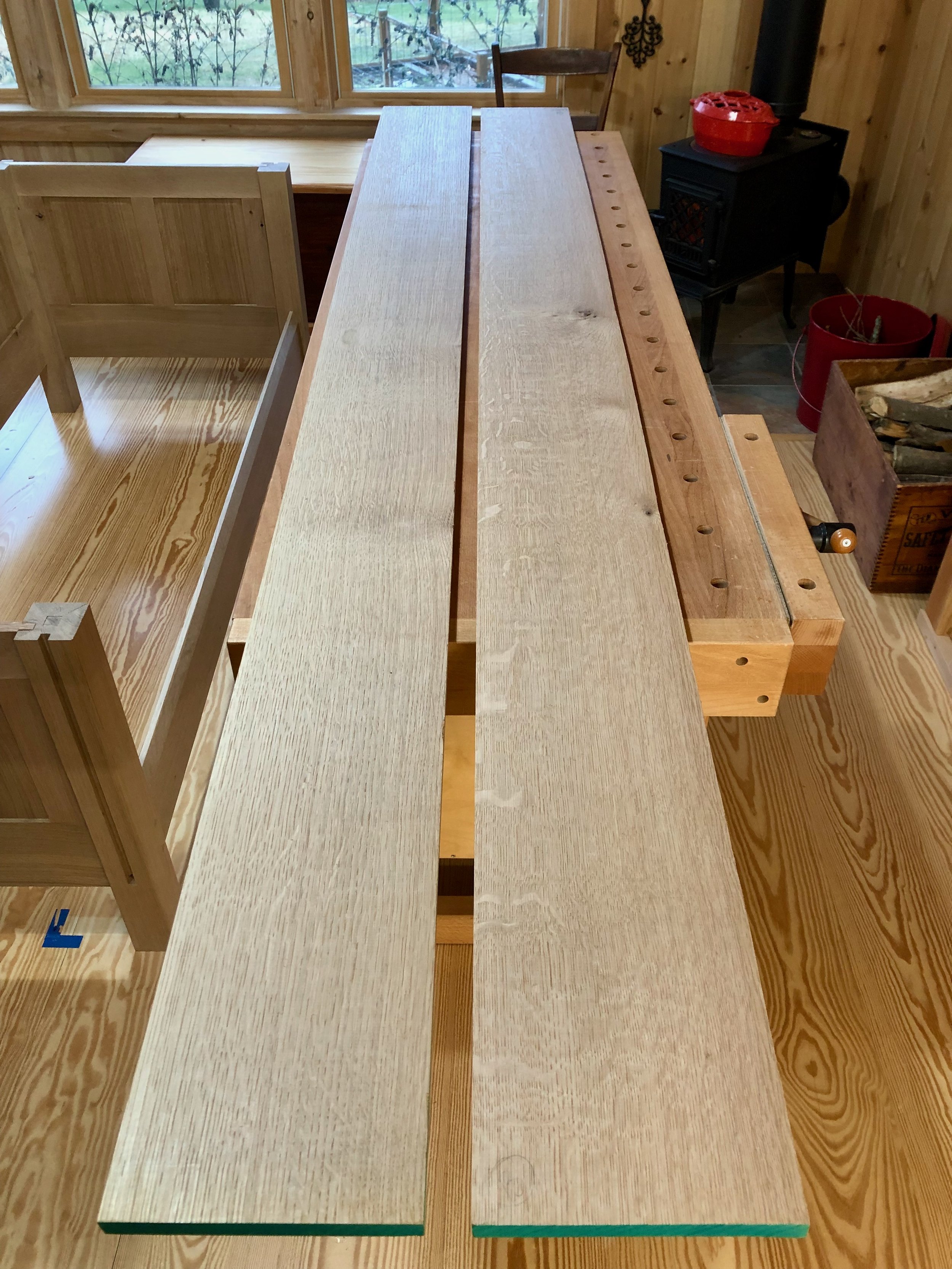
Arm boards
Job 1: Corbels
Corbel is an architectural term describing any projection that juts from a wall to support the weight of an element above it. The arms of No. 220 are supported by the settle’s frame with assistance from seven such corbels spread along the perimeter. Though eye-appealing, these members serve an important function or else they would not belong on a Craftsman design. The plan calls for six corbels of identical dimensions and a seventh, slightly larger one, placed along the center of the paneled back side. I sketched the designs free-hand on card paper after examining pictures of authentic examples (which, again, differed somewhat from the published plans).
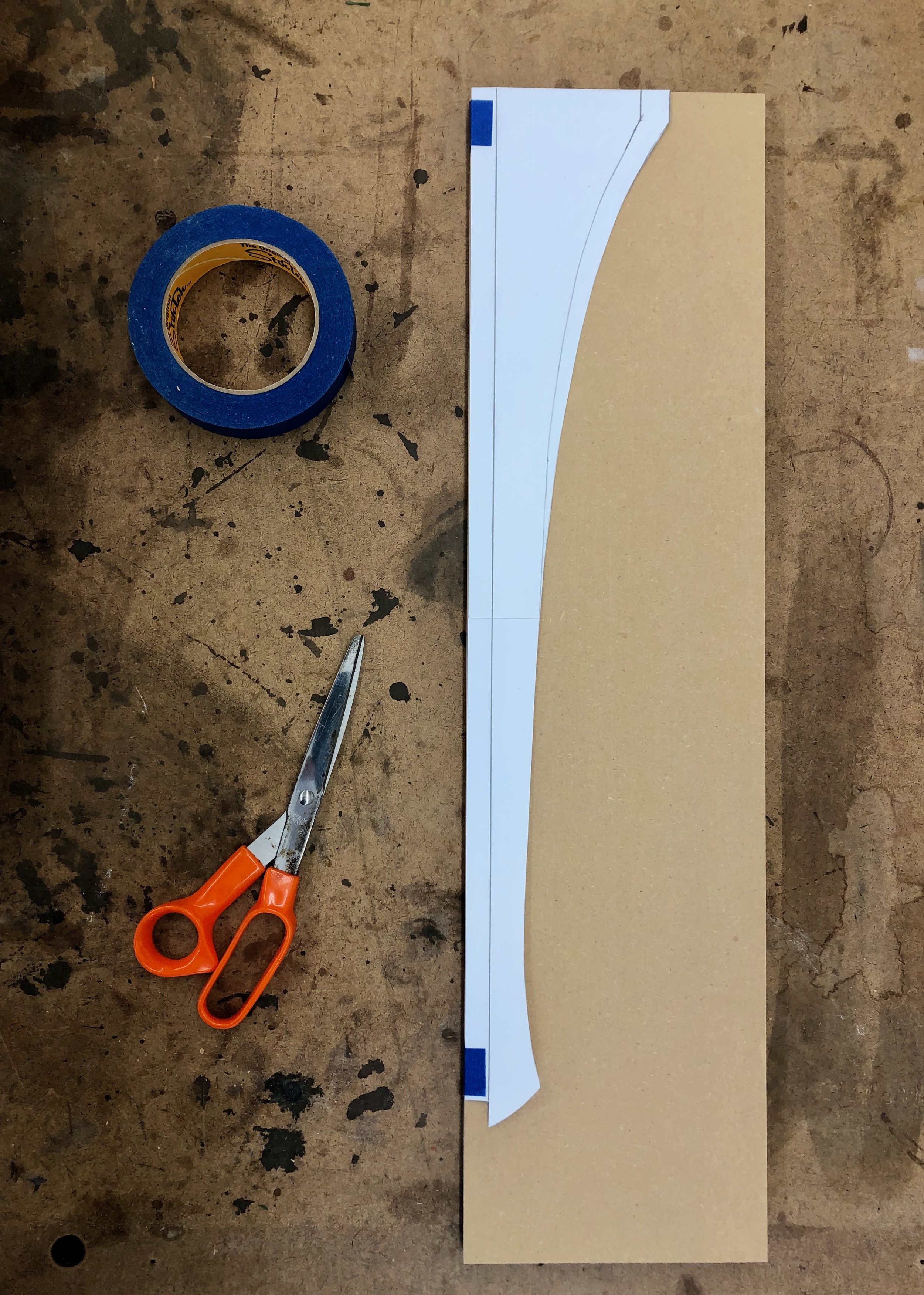
Corbel profiles sketched on paper
The larger template was traced onto 1/2 inch mdf board stock and the paper was then trimmed back to the smaller template which was also traced. Next, the mdf template versions were cut-out at the bandsaw and the curves shaped smooth “to the line” using a drum sanding bit on the drill press. These two new “patterns” were then used to trace their shapes (1 large, 6 small) onto prepped white oak boards and the shapes were cut-out at the bandsaw as before. I tried to stay about 1/16th of an inch outside the lines during these cuts.
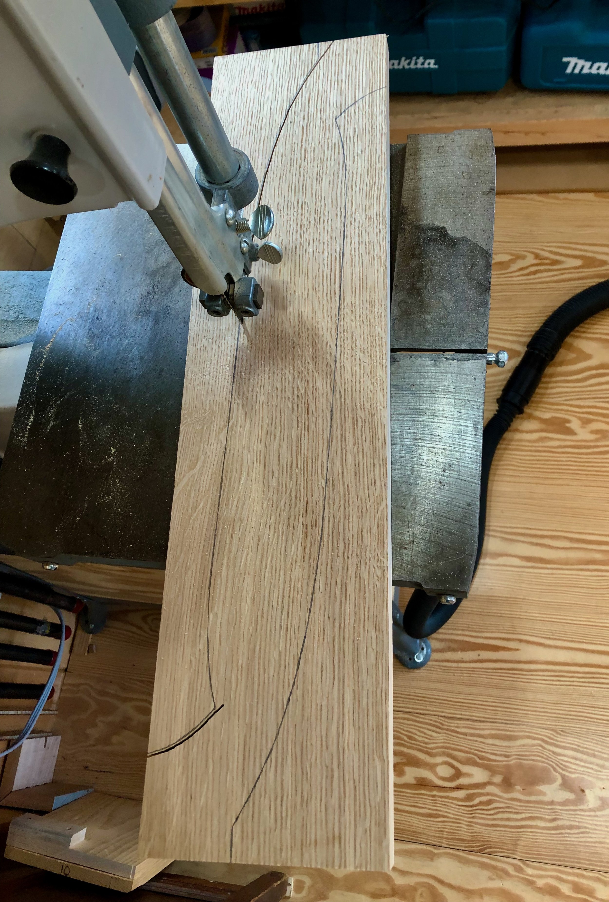
Cutting out the corbels, two per board
Next, the wood needed to be cleaned-up. A card scraper and 150 grit sandpaper were used to smooth the flat surfaces, whereas, the “cut” edges would be shaved to the line using a flush trimming bit at the router table. In this operation, the mdf patterns made earlier would serve as guides for the roller bearing to ensure that all curves ended up exactly matching the originals. I glued a couple of lips to the mdf patterns that allowed these to be temporarily affixed with screws to the corbel about to be shaped. Worked out well … except that on a couple occasions that little flare near the bottom was, unfortunately, clipped-off in the process. Tear-out like this is sometimes hard to avoid, and the quarter sawn grain orientation only made things easier to rip away. No problem, I just penciled a shallower “upturn” on these two defectives and then drum sanded to the line on the drill press. They say much of woodworking is actually “correcting mistakes”. These’ll look just fine.
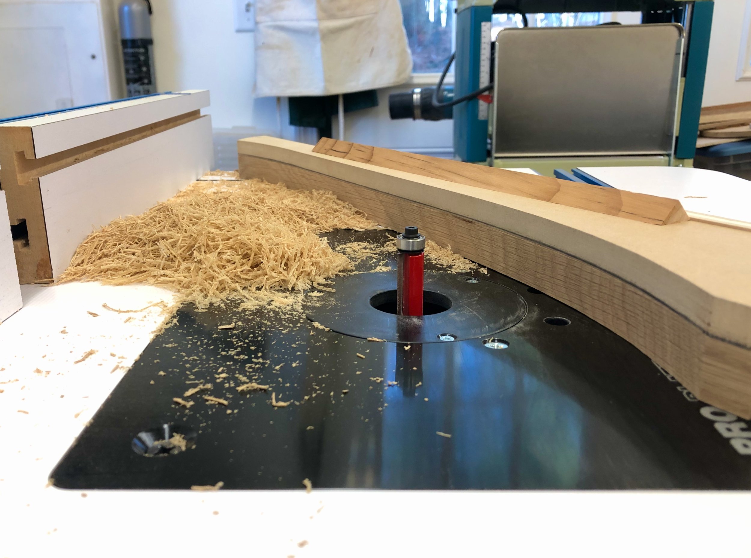
Shaping the corbels to pattern with a flush trimming router bit.
All that remained was to create tongues along the back edges for these parts to mount within the previously grooved legs and central stile. This was done using the dado blade on the table saw. Following a final trimming for fit, the corbels were ready for assembly.

No. 220 corbels
Job 2: Arms
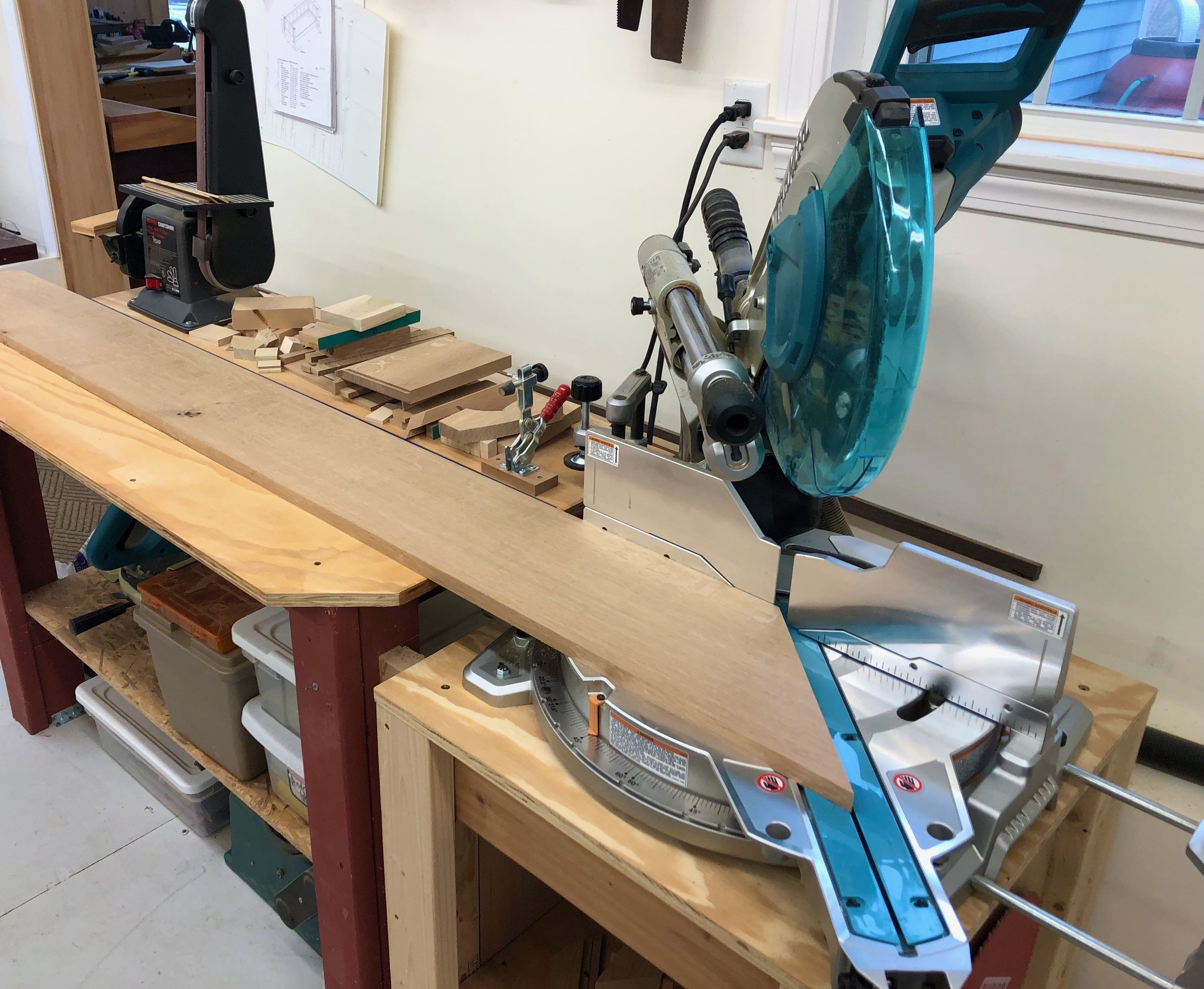
These should be easy. The final dimensions are all in hand: the arm lengths are determined by the as-built frame dimensions; and the 7 3/4 inch arm widths were prescribed by the plan. It all comes down to the order of operations and execution of tactics; in short, properly sawing the four 45 degree angle miter cuts. The goal here is to have a uniform looking seam, and one that is as tight as possible. My strategy was to cut one end of the back, say the “right-hand” side, and the corresponding right arm and try to get that joint “correct” before tackling the other side. That way, if a recut is needed, I would still have length to play with along the back. Should everything go as intended each of the corner angles sum to 90, but any deviation from 45 degrees in this first cut would need to be compensated for in the second if both the 90 degree angle and a tight & true seam are to be formed. I’m not sure why this situation bothered me so much before any cutting occurred, maybe its just the scale of things (an 11 inch hypotenuse!). Anyway, because of that scale I decided that the sliding miter saw was the machine to use for making the cuts.
To get started, the board stock was ripped to the correct width and the edges jointed square. Things are too cramped in the workshop to wield a 7 foot board at the jointer and so an antique No. 7 Stanley jointer plane, once belonging to my great-grandfather, was used to square the edges. Andrew restored this beauty a few years ago and it provides smooth & faithful service whenever called upon.

100+ year-old Stanley No. 7 plane and arm board
Time to do some cutting. The first miter was sawn on the back arm and then things got hairy. Not only was it not the perfect 45 degree angle set at the sliding miter saw, the cut, itself, was a bit “hollowed-out” in the center. What’s going on here?!
Cutting the back arm miter
I cut the second board and, again, things were just not right. While these were not fatal imperfections they would need to be fixed before joining. Maybe I should have paused at this point and just switched to using a track saw, but instead I took the route of fashioning a shooting board to correct the situation. Shooting boards are handy shop jigs that are easy to construct. They are used to guide a hand plane tilted on edge to cut along end-grain wood and I always thought I might need one to smooth the sawn edges before joining - only now it was required to also rescue the integrity of the angle, itself. Most 45 degree angled shooting boards are rather small, used primarily to shave the ends of picture frame stock. The challenge in this case was making a shooting board that could accommodate an 11 inch “shave” at the end of a 7 foot board. The typical design was a non-starter for this scale, but the key mechanical features could be preserved in a temporary set-up constructed from a few oak boards, screwed together and then clamped to the surface of my workbench (see below).

Shooting “board” set-up, in use
This “jig” worked surprisingly well. With a re-sharpened plane iron and some patience the skewed quarter sawn end grain was brought back to a flat 45. Not knowing the cause of the original error, I proceeded as planned: cutting at the sliding saw and beautifying that result as best I could at the shooting board until both of the corner joints passed inspection. I have since discovered a mechanical mis-alignment between the saw’s blade and the sliding arm. The machine is currently undergoing rehabilitation at the local Makita service center. I know, ‘it’s a poor carpenter that blames his tools’ - but they should, at least, meet you halfway!
Assembly
One final modification prior to assembly: biscuit slots. “Biscuits”, mentioned in earlier Projects, are football-shaped wooden wafers that assist glue joinery in two ways: 1. by providing a mechanical alignment between two pieces; and 2. by furnishing face-grain mating surfaces, which is particularly valuable when, as in this case, the joint involves end-grain wood - a notoriously poor glue bonding surface. I cut two biscuit slots into each of the angled ends with my handy biscuit joiner. Glue applied into these slots and unto the faces of the biscuit wafers will furnish a strong bond “within” the joined arm sections. I also cut three such slots into the upper rail and back arm board to ensure proper register here during assembly.
Final assembly of the arms would occur on top of the frame. The main object here was to attach the three arm pieces together, paying particular attention to the mitered seams, and since I needed a flat area to do this, it was either the frame or the floor. Also, since the assembled “U”-shaped arm structure would be rather fragile and unwieldy to handle afterwards, I decided to glue the arms to the frame at the same time. This necessitated mounting the supporting corbels in place too and so the whole thing was glued in a single session with assistance from my son, Ben. It went pretty well. I clamped and glued the long back arm section and its corbels to the frame first. After a 45 minute cure this gave a stable base for attachment of the remaining pieces, and it also allowed me to liberate and re-purpose some clamps - always a limiting resource. Next, the remaining corbels and side arms were glued into place. No drama (whew!).

All parts glued securely in place
The clamps were removed the following day and everything looked as it should. To complete the arms, the surface was sanded lightly with an orbital sander and then all of the sharp edges surrounding the arms were broken using a sanding block. A final hand-sanding over all surfaces (150 grit) made everything smooth and ready for finishing.
